计算机硬件编程复习整理
FPGA基础
PLD,FPGA,CPLD概念
PLD,Programmable Logic Device,可编程逻辑器件
FPGA,Field Programmable Gate Array
,现场可编程门阵列
CPLD, Complex Programmable logic device,复杂可编程逻辑器件
CPLD,FPGA都属于PLD
FPGA相比其他芯片的优势
并行(高性能),可编程可擦写,设计灵活,开发周期短
什么是FPGA
PLD,Programmable Logic Device,可编程逻辑器件
ASIC,Application Specific Integrated Circuit,专用集成电路
FPGA是一种可编程逻辑器件
可编程:FPGA所执行的功能是由客户定制且可以根据需求改写的
CPU 上的编程,本质上只能改变 CPU 状态寄存器的数值,不能改变 CPU
中的逻辑门单元之间的硬件逻辑。而 FPGA 是可以的
FPGA芯片工作原理
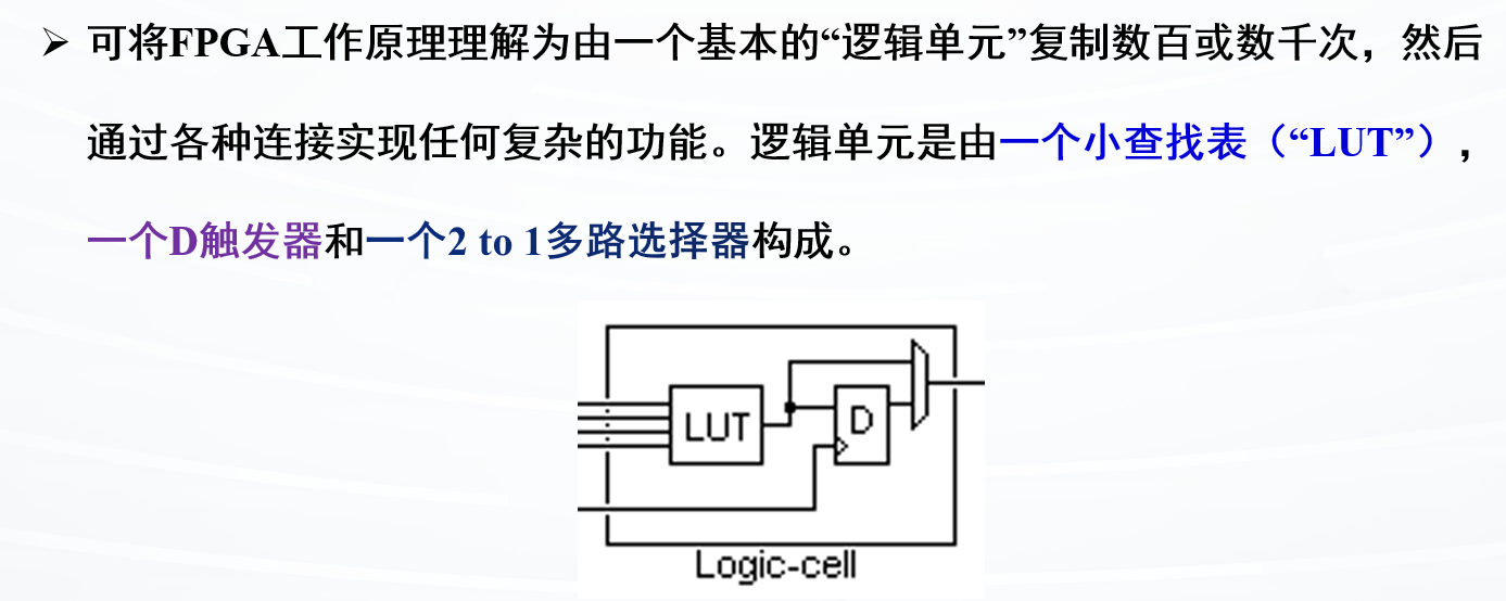
查找表LUT
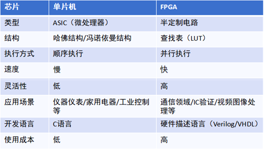
FPGA和其他芯片区别
不同的芯片采用的架构不同,FPGA是查找表结构,其他芯片多为冯诺依曼或哈佛结构,都有擅长的领域也都有短板
FPGA的特点就是并行执行 ,这个是 FPGA 的最大优势
FPGA特点
Verilog基础
掌握Verilog基本语法
掌握端口类型声明
掌握Vivado软件的使用
掌握简单设计代码与测试文件testbench的编写
Verilog HDL 语言基础
硬件描述语言HDL (Hardware Description Language )
是一种用形式化方法描述逻辑电路和系统的语言,是站在硬件角度进行编程的语言。是目前主要的电路设计输入方式
可以用一系列的编程模块 来逐层实现极为复杂的逻辑系统功能(类似于其他编程语言的函数调用、逐步搭积木思想)
和C语言的区别
Verilog 是硬件描述语言,在编译下载到 FPGA
之后,会生成相应的电路
C 语言是软件语言,编译下载到单片机/CPU
之后,还是软件指令,而不会根据你的代码生成相应的硬件电路,而单片机/CPU
处理软件指令需要取址、译码、执行,是串行执行的
Verilog 和 C 的区别也是 FPGA 和单片机/CPU 的区别,由于 FPGA
是并行处理 ,所以处理速度非常快,这个是 FPGA
的最大优势,这一点是单片机/CPU 替代不了的
模块声明
Verilog
HDL使用模块 (module)的概念来代表一个基本的功能单元
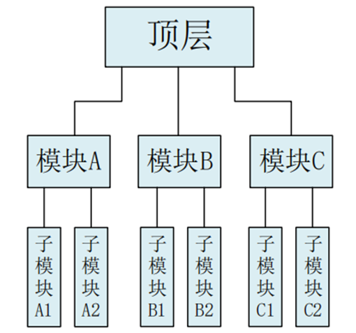
一个模块可以是一个元件,也可以是低层次模块的组合 。复杂的电路系统可由若干个子模块构成,即模块是可以进行层次嵌套的
一个模块是由各种电路组成,如组合逻辑电路+时序逻辑电路组合组成
常用的设计方法是使用元件来构建在多个地方都要使用的功能模块,以便进行代码重用,就类似于子函数的调用。大大提高工作效率,也便于修改子模块不会影响其他部分。跟搭积木一样慢慢搭出复杂的功能
模块设计思想
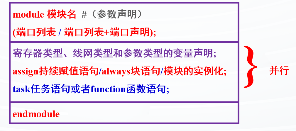
程序模板
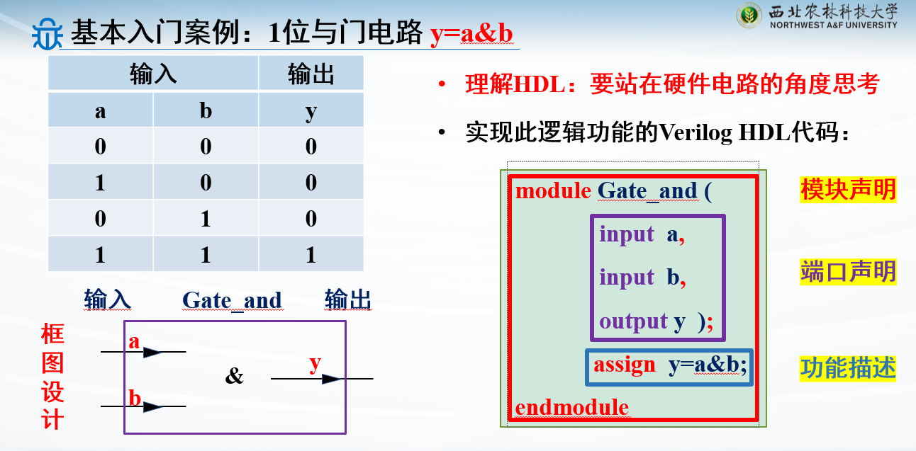
入门案例:1位与门电路
1
2
3
4
5
6
module Gate_and( input a, input b, output y); assign y=a&b; endmodule
注意,模块开始模块结束
还有模块的端口声明后面有分号;
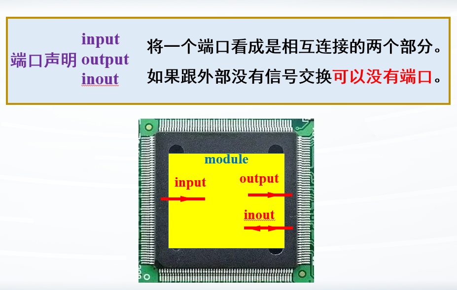
端口声明
端口声明,默认是wire类型
wire型
必须 用assign语句赋值:因为线型数据需要持续驱动
用法:wire [n-1:0] 数据名1,数据名2,…数据名M;
表示定义了M个wire信号,每条信号位宽为n。对应物理硬件上M*n条线
比如:
input wire [2:0] in
定义了input类型,wire类型(可以省略)的变量in
有3根线,即位宽为3,对应物理硬件中in[2], in[1], in[0]
三条线
input数据类型必须定义为wire类型
reg型
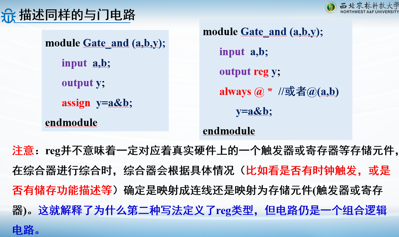
只能用always语句和 initial 语句中被赋值
如果该过程语句描述的是时序逻辑,即 always
语句带有时钟信号,则该寄存器变量对应为寄存器
如果该过程语句描述的是组合逻辑,即 always
语句不带有时钟信号,则该寄存器变量对应为硬件连线
用法:reg [n-1:0] 数据名1,数据名2,…数据名M;
在硬件上表示定义了M个寄存器变量,每个寄存器的位宽为n
比如:
reg [4:0] a, b, c;表示定义了3个寄存器a,b,c,每个寄存器的位宽为5;
位宽若不指定(如reg a,b,c;)就默认是1位
一定要注意寄存器类型只能用在always或者initial语句中
wire和reg的区别wire(线网)变量:可以理解为电路模块中的物理连线,特点是输出值紧跟输入值变化 ,需要持续的驱动。没有存储功能,只能用在assign赋值语句中
对代码进行仿真时,wire类型是不占用仿真内存。线网是被驱动的,该值不被保持,在任意一个仿真步进上都需要重新计算
reg(寄存器)变量:对应电路上的存储单元,变量保持最后一次赋值(有存储数据功能) ,因此不用持续驱动。只能用在always或initial语句中
对代码进行仿真时,reg类型的变量会占用仿真环境的物理内存。寄存器在被赋值后,便一直保存在内存中,保持该值不变,直到下一次被赋值。即reg一定要有触发,输出才会反映输入。
memory型
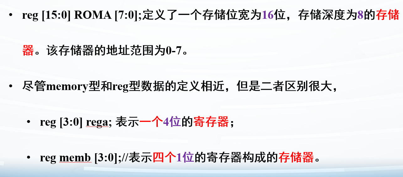
对reg型变量建立数组来对存储器建模,可以用来描述RAM
用法:reg [n-1:0] 存储器名 [m-1:0];
其中[n-1:0]定义了存储器中每一个存储单元的位宽大小,即该存储单元是一个n位位宽的寄存器
后面[m-1:0]定义了存储器的大小,即有m个这样的寄存器
快捷记忆方法:写在前面的表示位宽,写在后面的表示个数
memory和reg区别
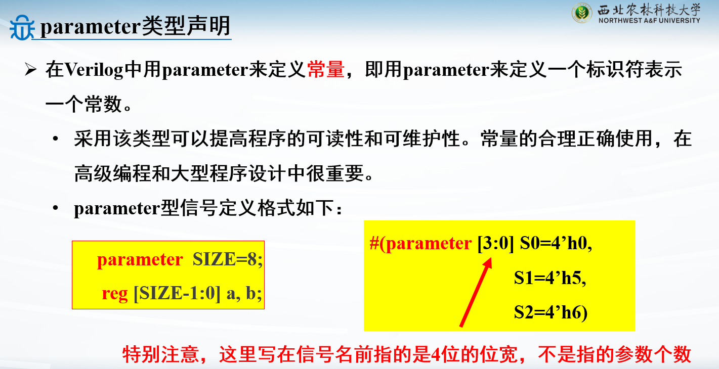
parameter常量声明
用#写在端口声明前面
注意,#写在(parameter)前
模块总结
对一个模块来说:
输入只能是wire
输出可以是wire,也可以是reg
电路功能描述
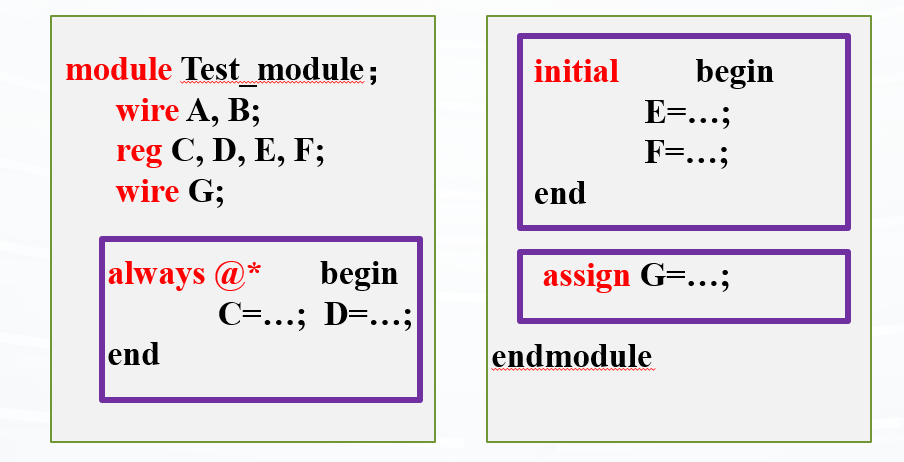
同一个模块里的assign, always, initial语句块并行执行
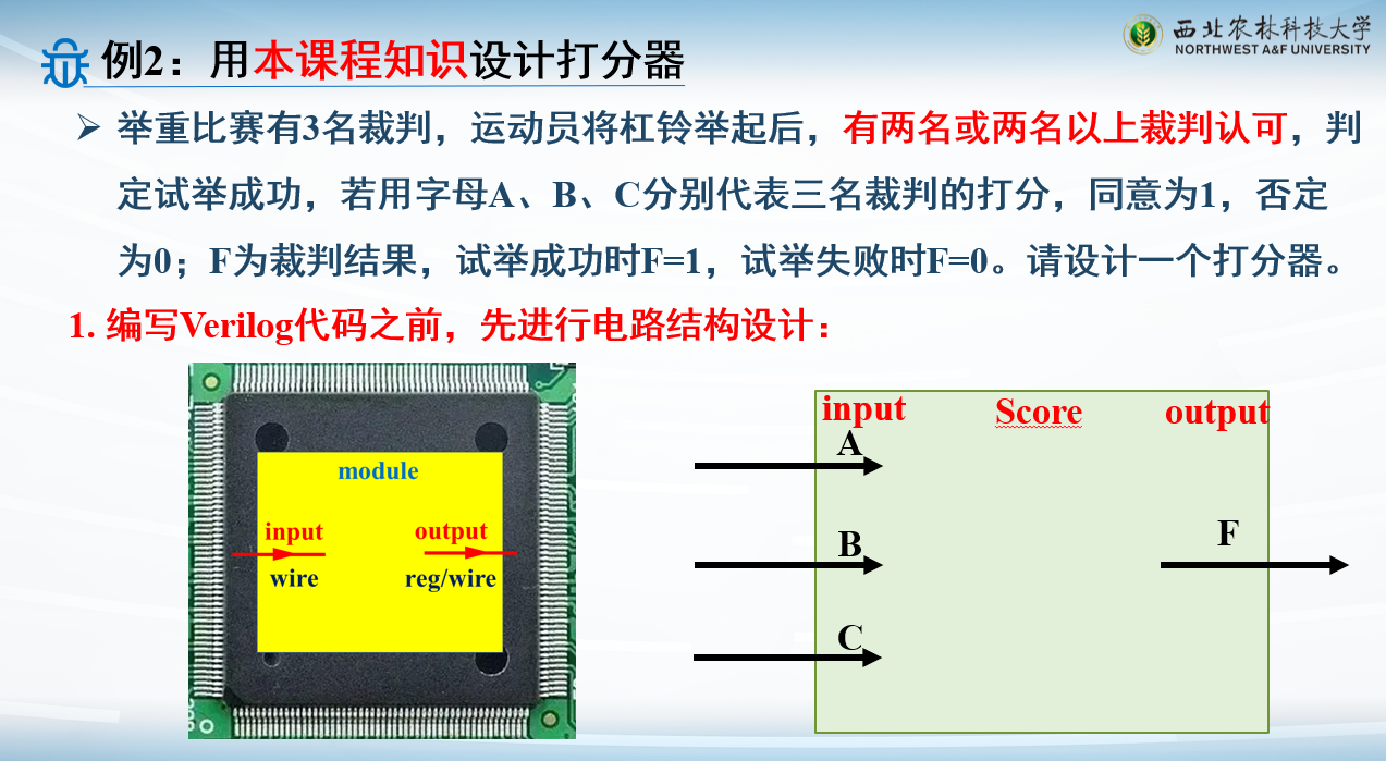
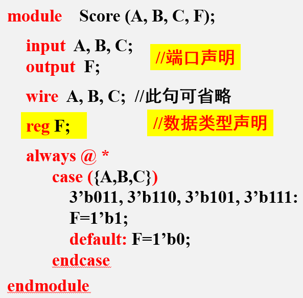
例子:打分器
F=1'b1:1'b为一位二进制,第二个1表示赋值的1
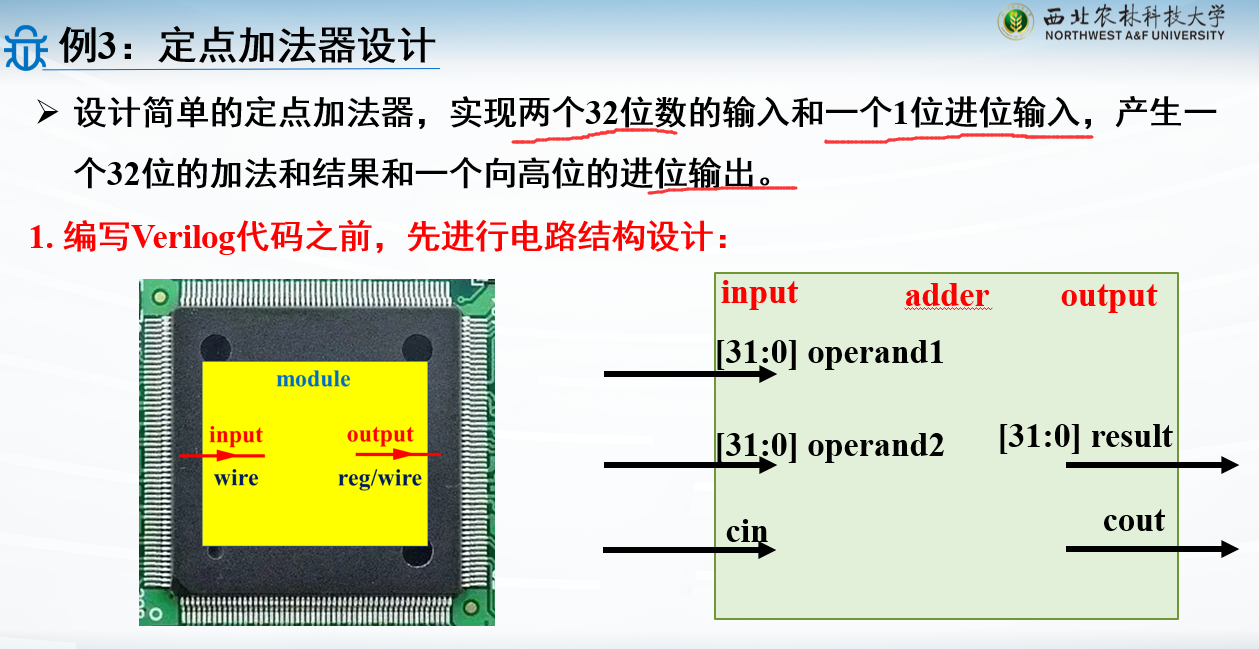
例子:定点加法器
1
2
3
4
5
6
7
8
9
10
module adder( input [31 :0 ] operand1, input [31 :0 ] operand2, input cin, output [31 :0 ] result, output cout ); assign {cout,result} = operand1 + operand2 + cin; endmodule
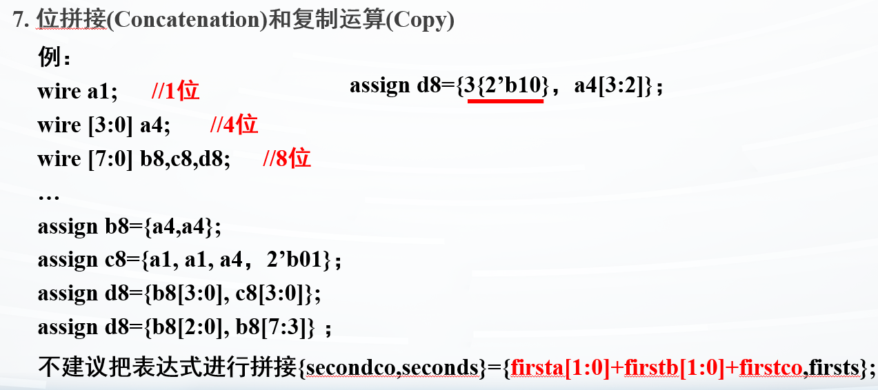
{}表示拼接,此时最高位就会赋值给cout
testbench的编写
描述测试信号的变化和测试过程的模块称为测试平台(testbench)
说到底就是对写好的模块进行调用
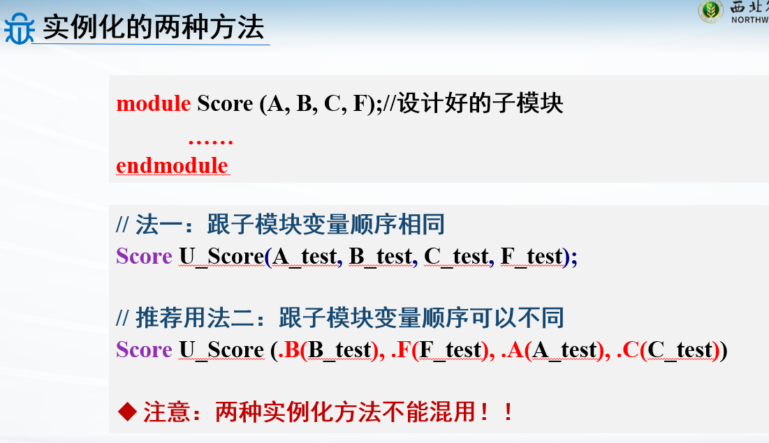
实例化的方法:
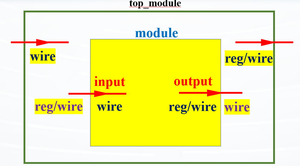
模块调用时数据类型的声明
对一个模块来说,从外界的输入必须是wire,输出到外界的可以是wire也可以是reg
但是调用模块时,你用来传进去的变量就得反过来
测试打分器模块:
1 2 3 4 5 6 7 8 9 10 11 12 13 `timescale 1ns / 1ps module Score_test ; reg A_test, B_test, C_test; wire F_test ; Score U_Score(A_test, B_test, C_test, F_test); initial begin A_test=1 ’b0; B_test=0 ; C_test=0 ; end always #5 A_test=~A_test; always #7 B_test=1 ; always #4 C_test=~C_test; initial #100 $finish ; endmodule
测试加法模块:
1 2 3 4 5 6 7 8 9 10 11 12 13 14 15 16 17 18 19 `timescale 1ns / 1ps module tb_addr; reg [31 :0 ] operand1,operand2; reg cin; wire [31 :0 ] result; wire cout; adder uut (.operand1 (operand1),.operand2 (operand2), .cin (cin),.result (result),.cout (cout)); initial begin operand1 = 0 ; operand2 = 0 ; cin = 0 ; #100 $finish ; end always #10 operand1 = $random ; always #10 operand2 = $random ; always #10 cin = {$random } % 2 ; endmodule
#10表示等10个单位时间
Verilog语法基础
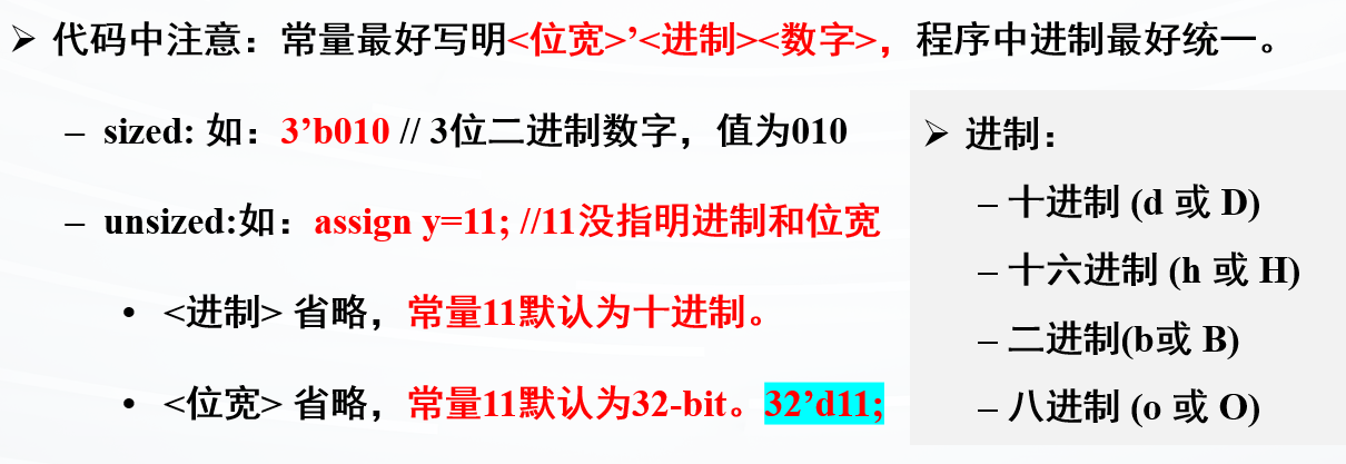
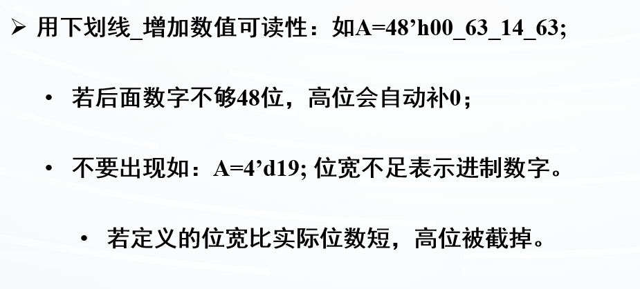
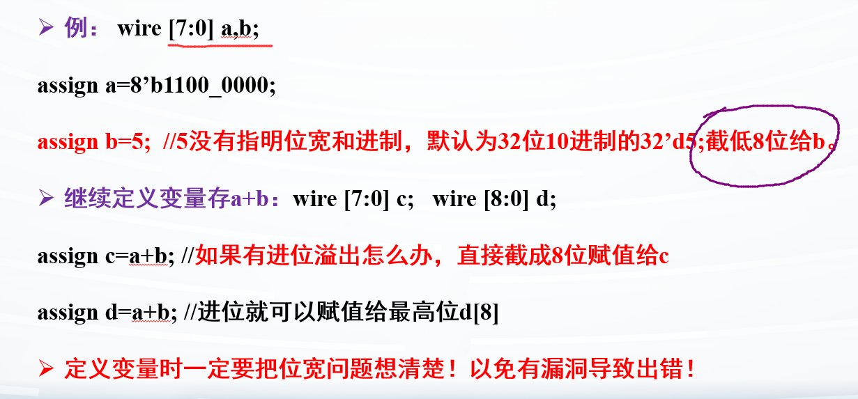
数制与位宽
最好位宽、进制都指定
注意:这里的位宽是针对二进制 的
位宽默认32位
进制默认10进制
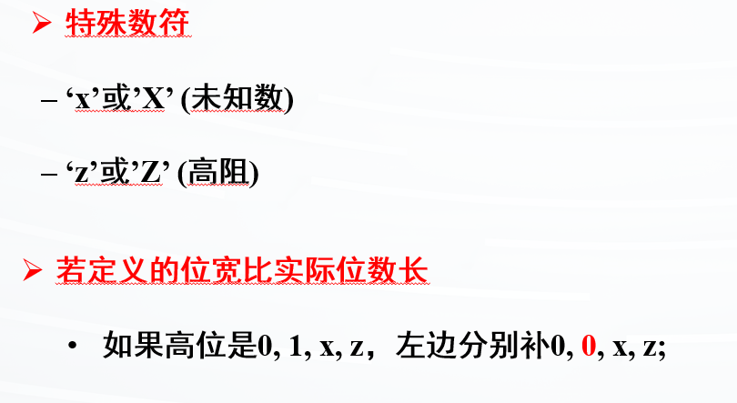
特殊字符
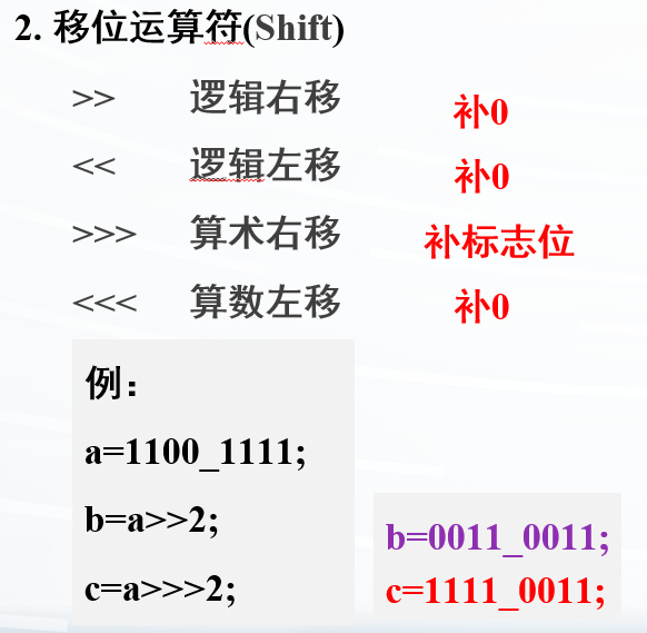
运算操作
跟C语言差不多
**为幂运算
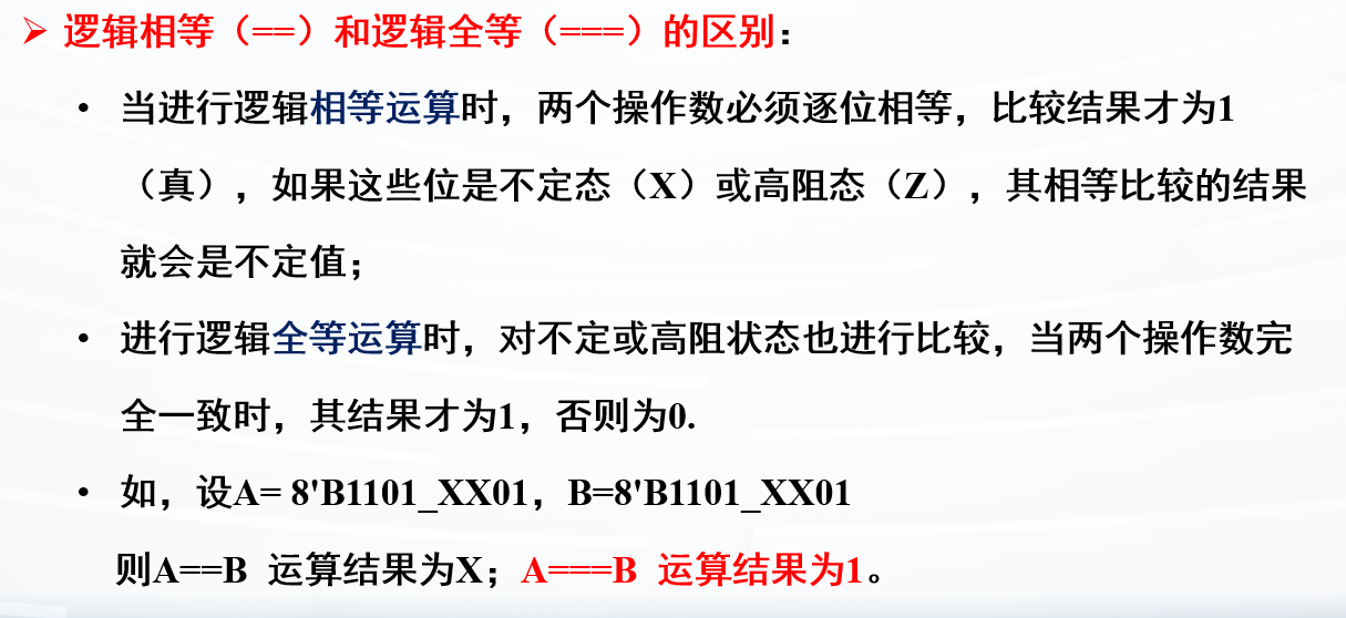
==不考虑不定X和高阻Z
===考虑
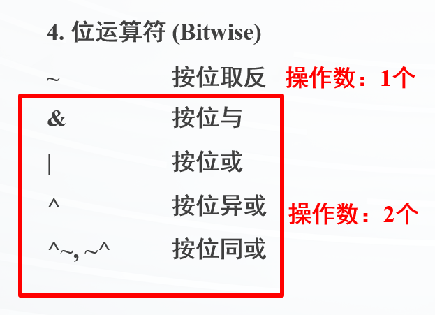
位运算:
注意^是按位异或
注意按位与和逻辑与
位拼接{}
组合逻辑电路设计
掌握always块的用法
掌握条件和循环语句用法
掌握常数和参数的使用
理解阻塞和非阻塞赋值区别
理解verilog语言和c语言的区别:并行和顺序执行
组合逻辑与时序逻辑
数字逻辑的分类从本质上可分为组合逻辑 和时序逻辑 两大类
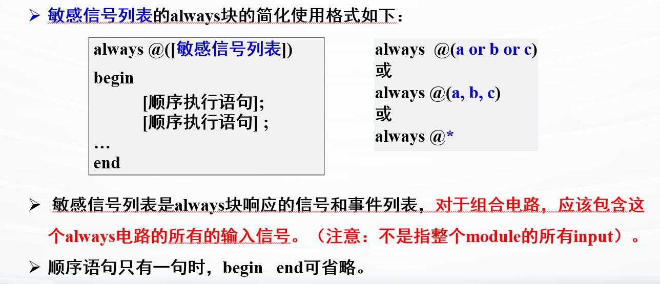
两个逻辑的alway@的内容不一样
组合逻辑
用法:always @* 或
always @ (这块电路的敏感信号列表)
组合逻辑电路在任意时刻的输出只取决于当前时刻的输入,与电路之前的状态无关
时序逻辑
用法:always@ (posedge clk or negedge reset) 或
always@(clk)
组合逻辑的alway块
组合逻辑 电路中,Verilog
使用一些顺序执行 的过程语句来进行行为描述
这些语句用在一个always块或initial块中,但只有always块能够进行综合并生成能够执行逻辑运算或控制的电路模块
initial一般只用在仿真文件(testbench)中
敏感信号列表
敏感信号可分为两种类型:一种是电平敏感型 ,一种是边缘敏感型
组合电路一般采用电平触发
时序电路一般由时钟边沿触发。Verilog
HDL提供了posedge和negedge 两个关键词来分别描述上升沿和下降沿
过程赋值
过程赋值只能用在always块或initial块中
赋值有两种:阻塞和非阻塞
阻塞赋值
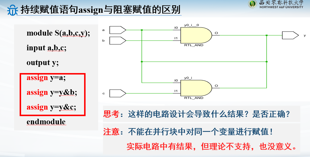
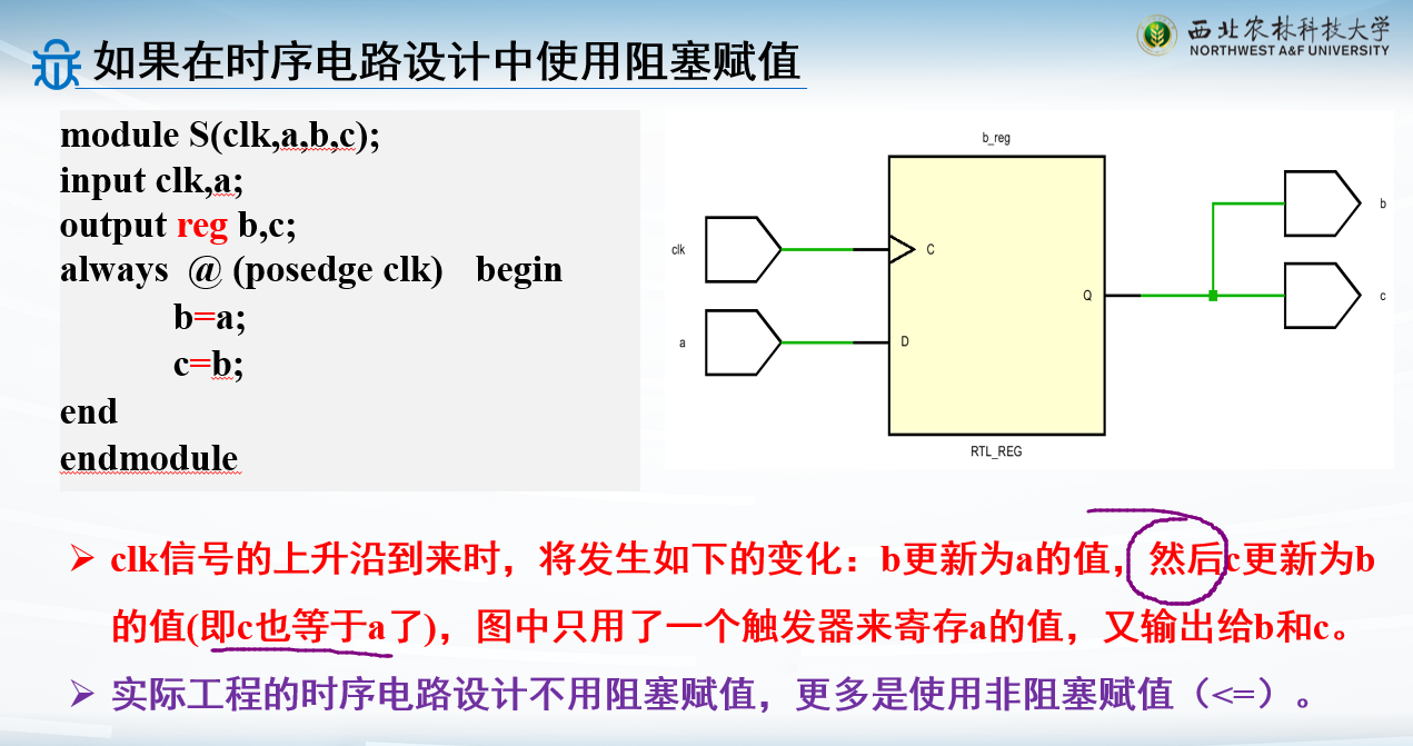
多在组合逻辑电路中使用阻塞赋值(=),信号的值在赋值语句执行完后立刻就改变
在同一个always
中,一条阻塞赋值语句如果没有执行结束,那么该语句后面的语句就不能被执行,即被“阻塞”
与C语言程序中的顺序执行过程类似
对比assign语句:
如果在时序电路用阻塞:
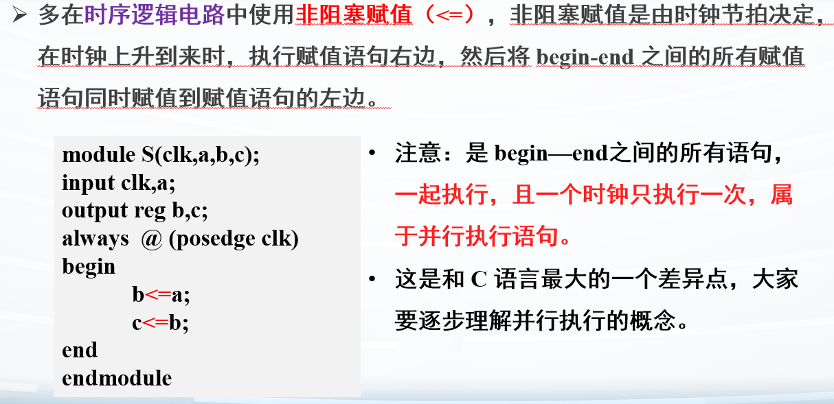
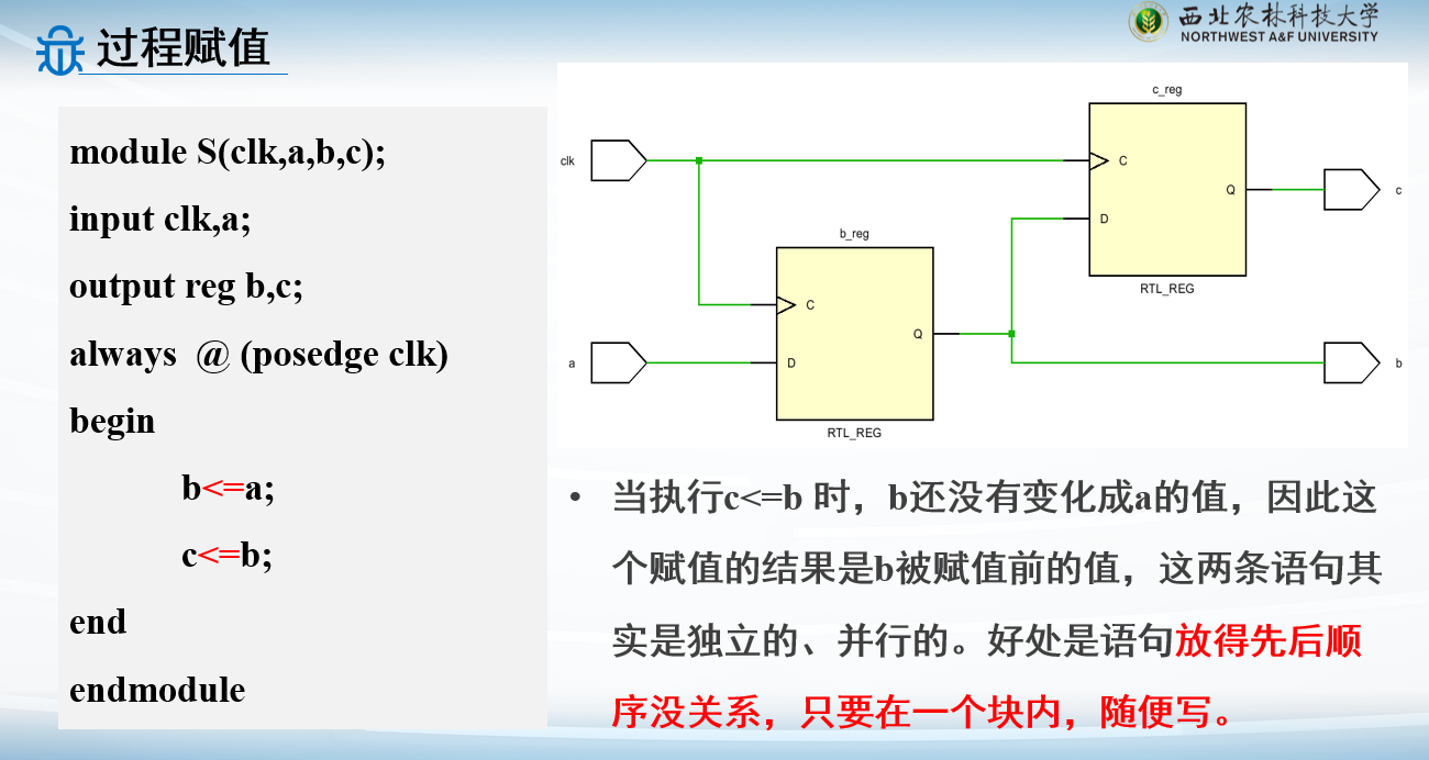
非阻塞赋值
这个是一起执行,并行
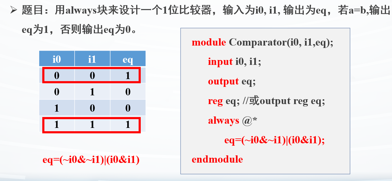
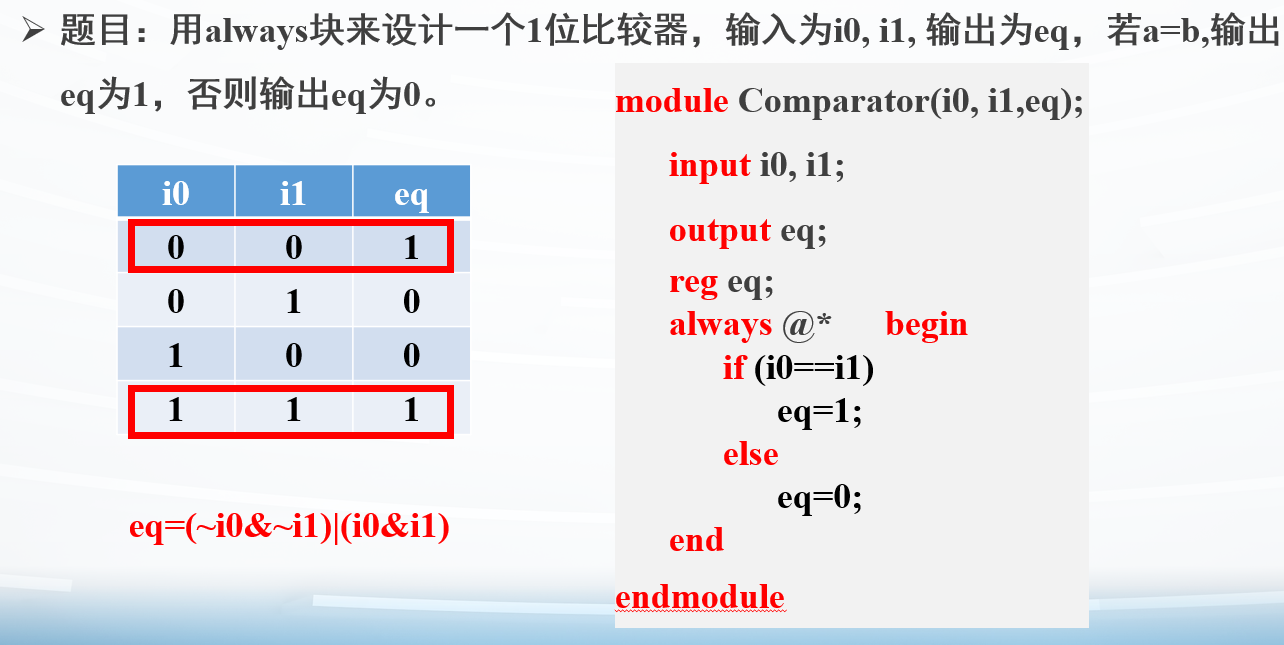
例子:1位比较器
条件语句
if-else
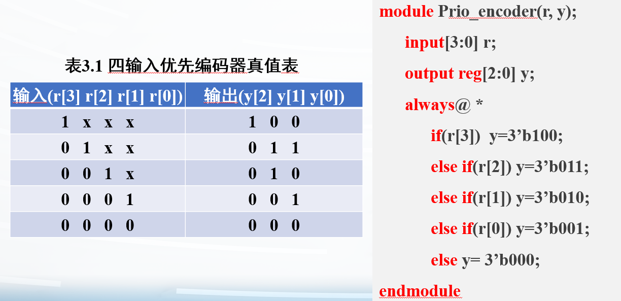
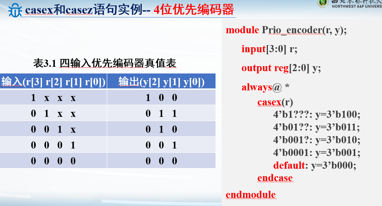
例子:4位优先编码器
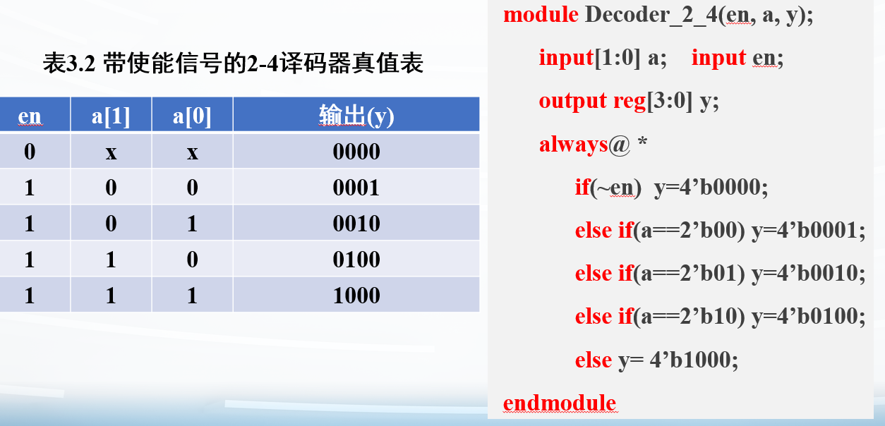
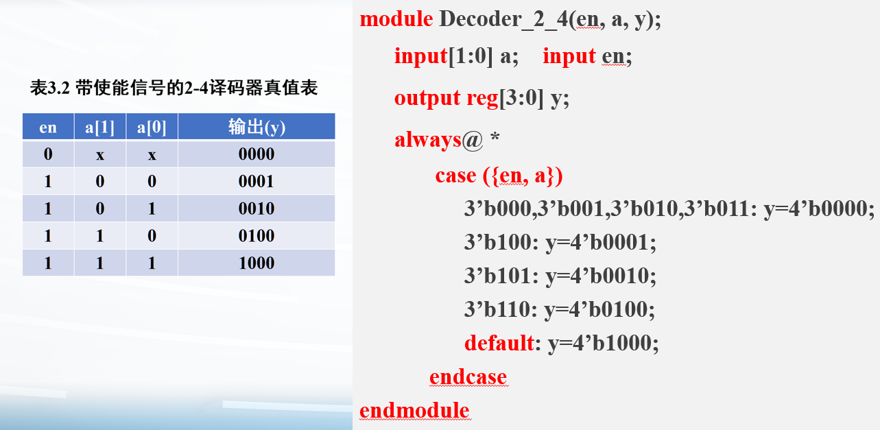
例子:带使能信号的2-4译码器
译码器:独热码,即0000, 0001, 0010, 0100, 1000
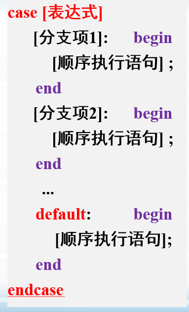
case
例子:带使能信号的2-4译码器
用拼接符{en, a}把这两个连接起来,可以直接判断
Verilog的case不需要像C语言一样加break;,也不需要有switch
仅有一个case()
case变体
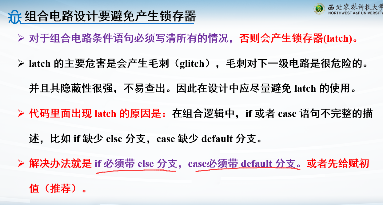
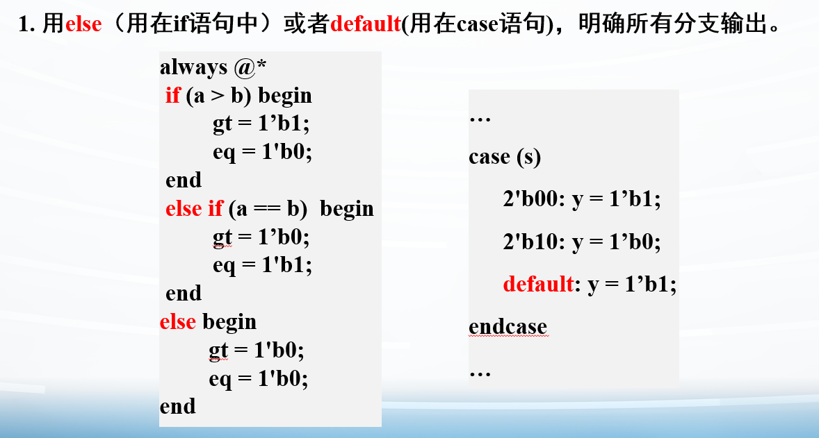
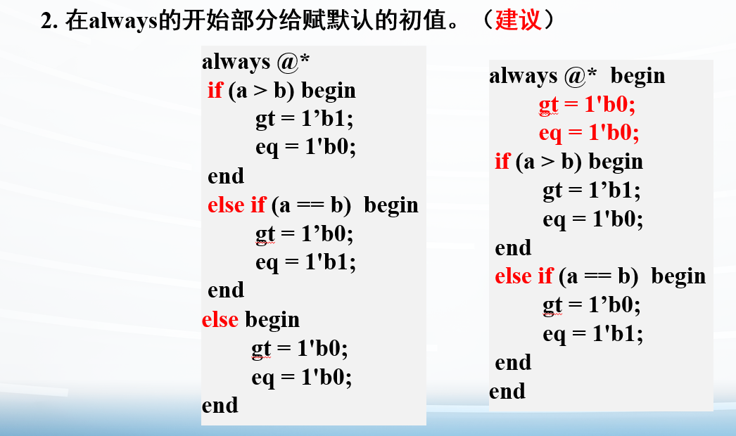
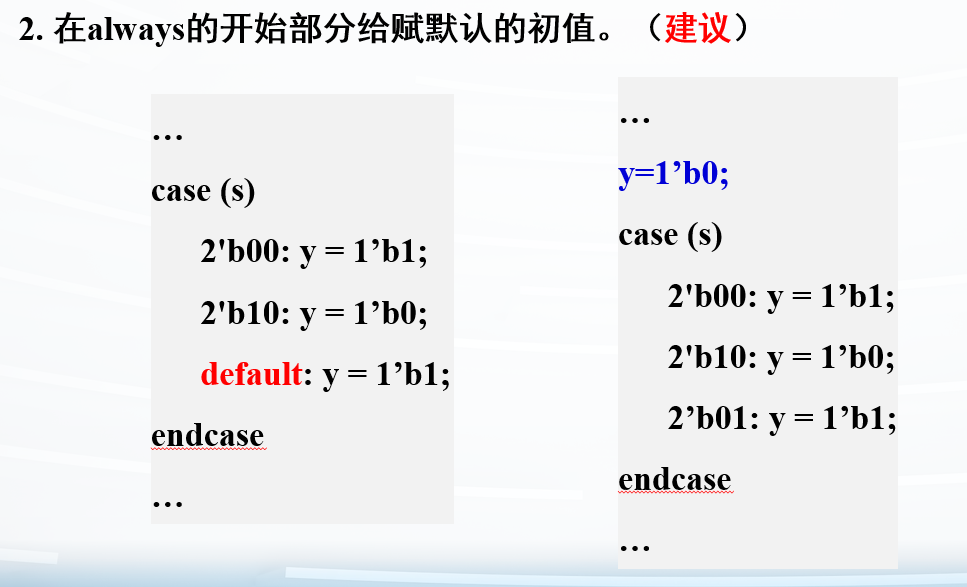
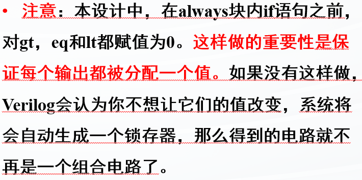
case语句要写清楚所有分支,如果没有所有分支,会生成存储元件,这不是我们在组合逻辑中需要的
未匹配的值,最好加default或赋初值
避免锁存器
循环语句
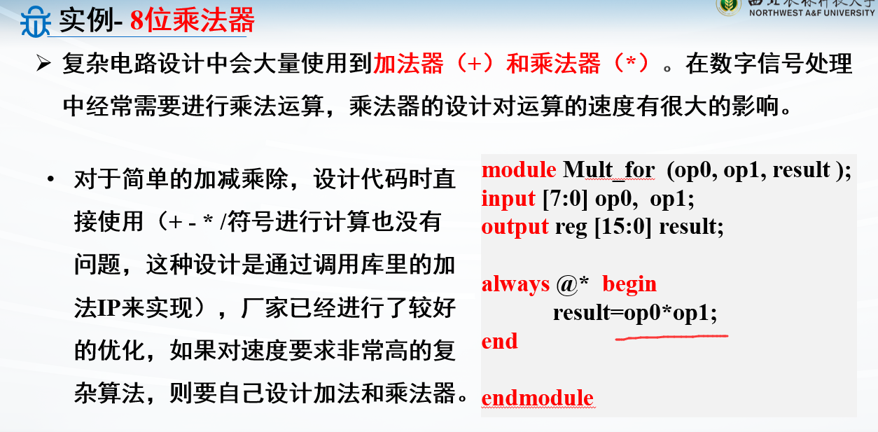
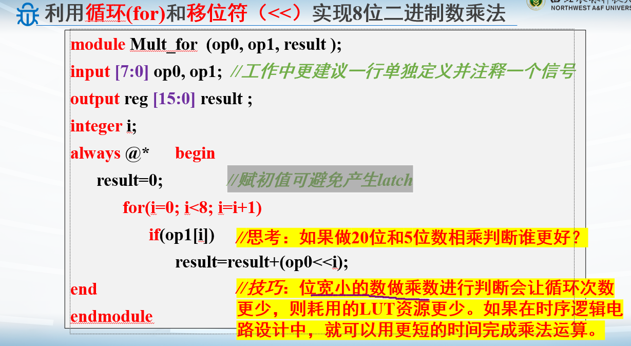
例子:8位乘法器-乘号运算
虽然*能实现,但是会占用更多资源
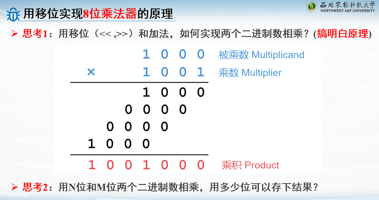
用移位实现8位乘法器
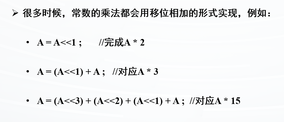
乘法可以用位移和加法实现
不用*乘法运算的原因
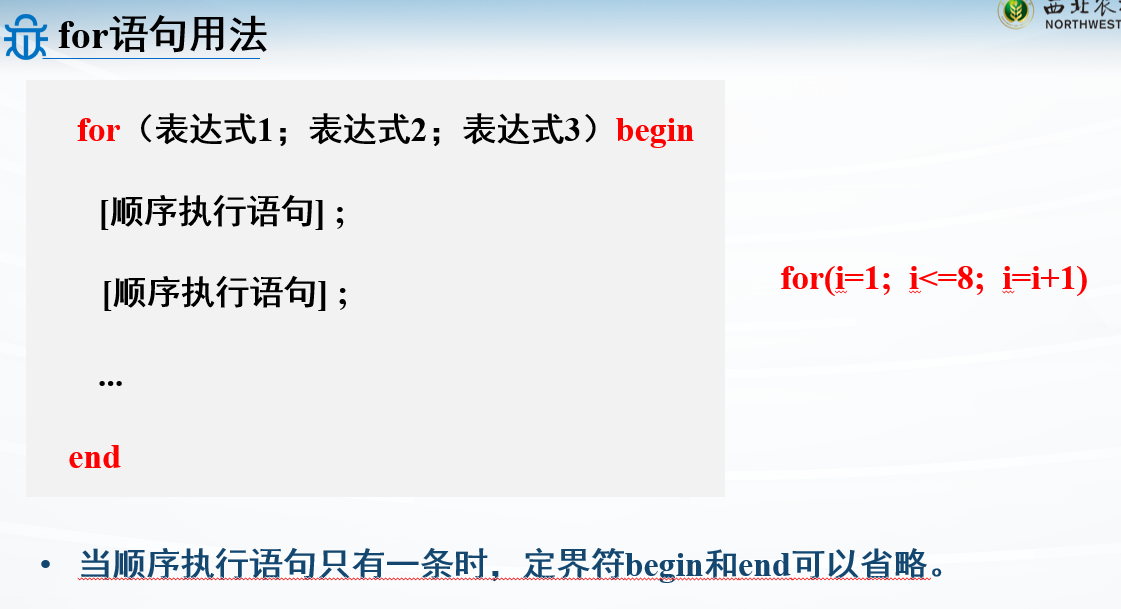
for语句
1
2
3
4
5
6
7
8
9
10
11
module Mult_for(op1, op2, result); input [7 :0 ] op1,op2; output reg [15 :0 ] result; integer i; always @* begin result = 0 ; for (i=0 ; i<8 ; i=i+1 ) if (op1[i]) result = result + (op2[i]<<i); end endmodule
repeat语句
1
2
3
4
5
6
7
8
9
10
11
12
13
14
module Mult_repeat (op0, op1, result);input [7 :0 ] op0, op1;output reg [15 :0 ] result ; integer i; always @* begin result=0 ; i=0 ; repeat (8 ) begin if (op1[i]) result=result+(op0<<i); i=i+1 ; end end endmodule
while语句
1
2
3
4
5
6
7
8
9
10
11
12
13
14
module Mult_while (op0, op1, result );input [7 :0 ] op0, op1;output reg [15 :0 ] result ; integer i; always @* begin result=0 ; i=0 ; while (i<8 ) begin if (op1[i]) result=result+(op0<<i); i=i+1 ; end end endmodule
always块一般编码原则
虽然Verilog与C语言语法相近,但是我们要谨记编写代码的目的是综合为硬件电路而不是用C语言描述顺序算法 ,做不到这些会经常导致无法综合的代码或者不必要的复杂实施,或者在仿真和综合之间产生差异
组合电路代码中常见的错误
变量不能在多个并行块中赋值(仿真文件中这么写,但是这种写法只适用于teshbench)
写always块,敏感信号列表直接写*可以避免
不完整分支会导致锁存器,所以可以赋初值,在if语句中用else,在case语句中用default
组合电路中always块的使用原则
参数和常数
常数localparam和参数parameter
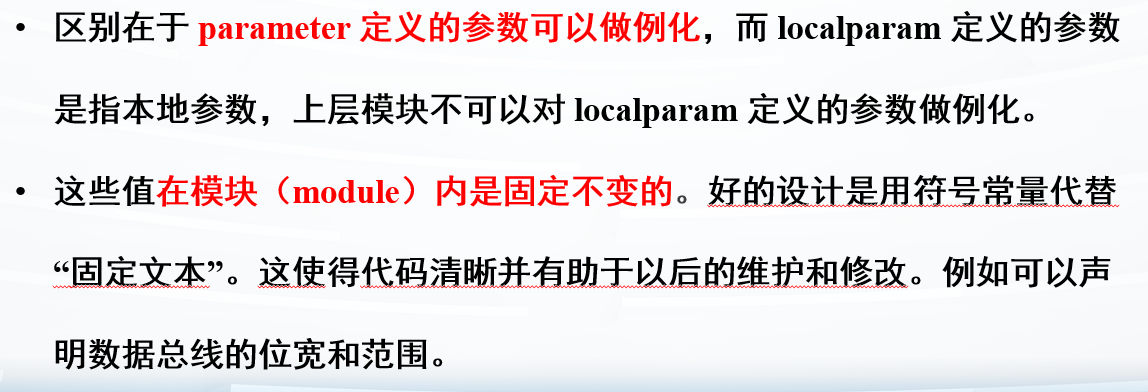
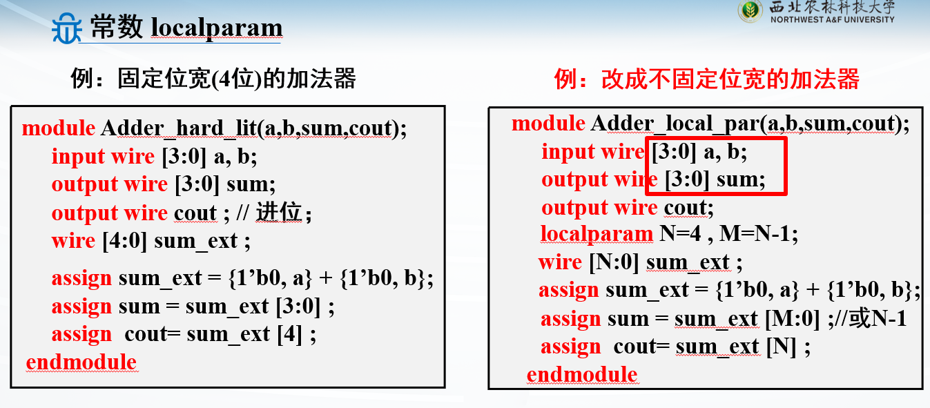
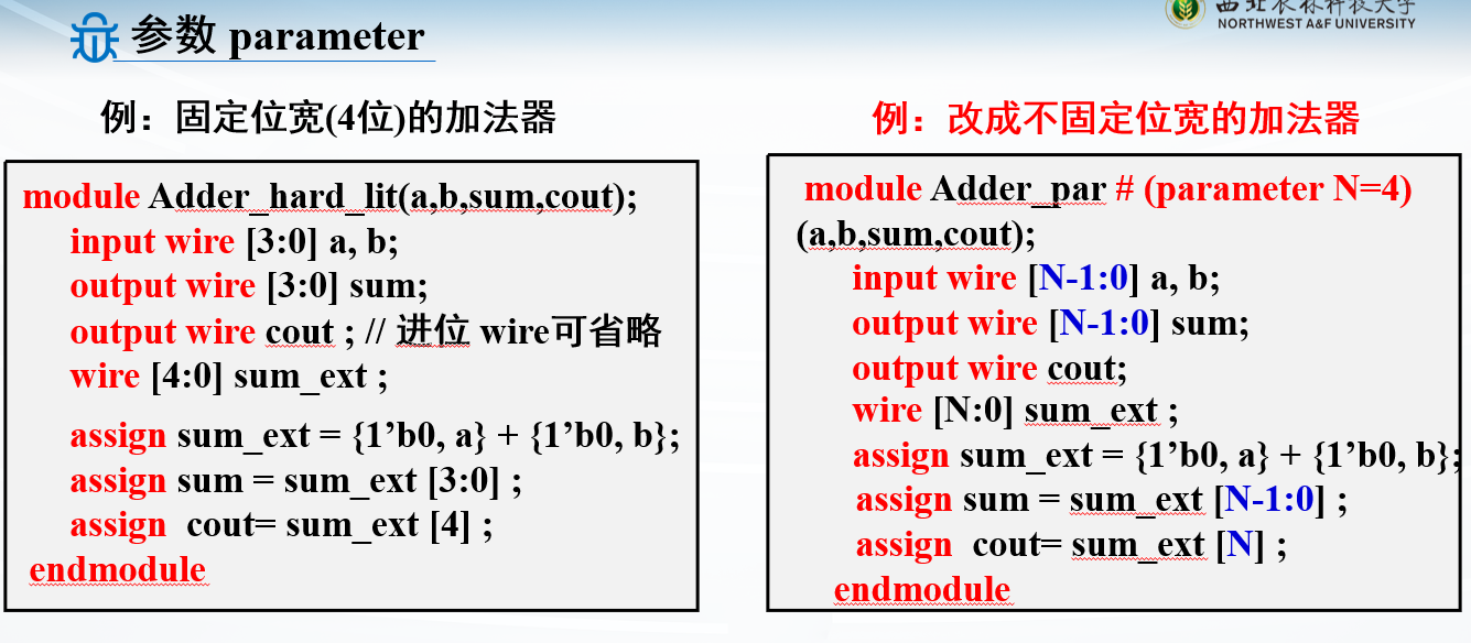
localparam用在端口声明之后,parameter可以用在端口声明之前,也可用在端口声明之后。分别类似于C语言中的const用法以及宏定义
localparam
我印象中没用过这个
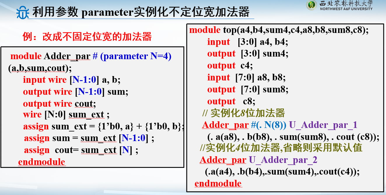
parameter
所谓不定位宽,就是用变量指明位宽,需要多少位就调用多少位
还能指定默认值#(parameter N=4)
常用组合逻辑电路设计实例
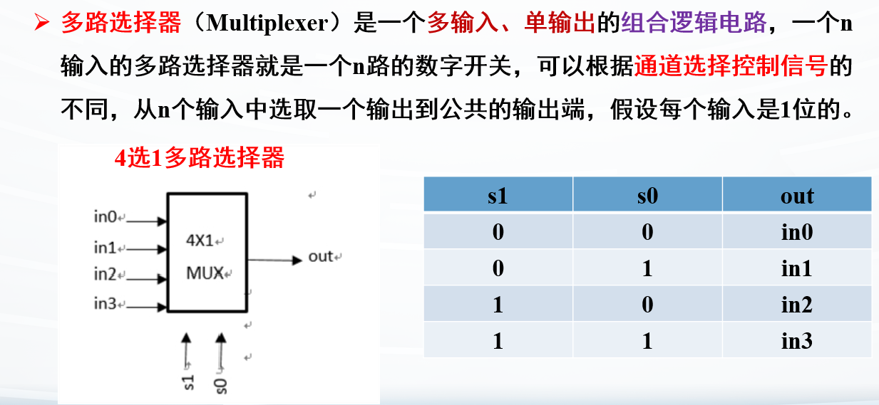
例子:多路选择器
从多个输入中选择一路
1
2
3
4
5
6
7
8
9
10
11
12
13
14
module Mux4_1(in0,in1,in2,in3,s1,s0,out); input wire in0,in1,in2,in3; input wire s0,s1; output reg out; always @* begin out = 0 ; case ({s1,s0}) 2'b00 : out = in0; 2'b01 : out = in1; 2'b10 : out = in2; default :out = in3; endcase end endmodule
注意模块声明后面的;
注意case语法
注意endcase语句
对应的testbench
1
2
3
4
5
6
7
8
9
10
11
12
13
14
15
16
17
18
module tb_Mux4_1(); reg in0,in1,in2,in3; reg s1,s0; wire out; Mux4_1 U_Mux4_1(.in0 (in0),.in1 (in1),.in2 (in2),.in3 (in3),.s1 (s1),.s0 (s0),.out (out)); initial begin in0=0 ; in1=1 ; in2=1 ; in3=0 ; s0=1'b0 ; s1=1'b0 ; #40 s0=1'b1 ; #40 s1=1'b0 ; #40 s0=1'b0 ; #100 $finish ; end endmodule
注意testbench最后加的#100 $finish;
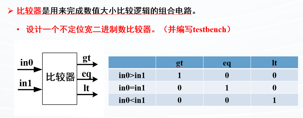
例子:比较器
不定位宽:#(parameter N=8)
1
2
3
4
5
6
7
8
9
10
11
12
module Comp #(parameter N=8 ) (in0,in1,gt,eq,lt);input [N-1 :0 ] in0,in1;output reg gt, eq, lt; always @* begin gt=1'b0 ; eq=1'b0 ; lt=1'b0 ; if (in0>in1) gt=1 ; else if (in0==in1) eq=1'b1 ; else lt=1'b1 ; end endmodule
对应的testbench
1
2
3
4
5
6
7
8
9
10
11
12
module tb_Comp #(parameter M=10 ) (); reg in0, in1; wire gt, eq, lt; Comp #(.N(M)) U_Comp(in0,in1,gt,eq,lt) ; initial begin in0 = 0 ; in1 = 1 ; #20 in0 = 100 ; #40 in1 = 77 ; #200 $finish ; end endmodule
注意,如果调用模块,写了parameter的会在变量名前 用
Comp #(.N(M)) U_Comp(in0,in1,gt,eq,lt);
译码器和编码器
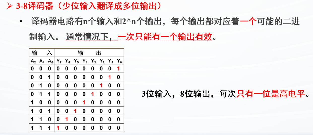
例子:3-8译码器
1
2
3
4
5
6
7
8
9
10
11
12
13
14
15
16
module Decoder (in,y);input [2 :0 ] in; output reg [7 :0 ] y;always @* begin case (in) 3'b000 : y=8'b0000_0001 ; 3'b001 : y=8'b0000_0010 ; 3'b010 : y=8'b0000_0100 ; 3'b011 : y=8'b0000_1000 ; 3'b100 : y=8'b0001_0000 ; 3'b101 : y=8'b0010_0000 ; 3'b110 : y=8'b0100_0000 ; default : y=8'b1000_0000 ; endcase end endmodule
对应的testbench:
1
2
3
4
5
6
7
8
9
10
11
12
module tb_Decoder(); reg [2 :0 ] in; wire [7 :0 ] y; Decoder U_Decoder(in,y); initial begin in = 3'b000 ; #30 in = 3'b100 ; #40 in = 3'b010 ; #20 in = 3'b110 ; #200 $finish ; end endmodule
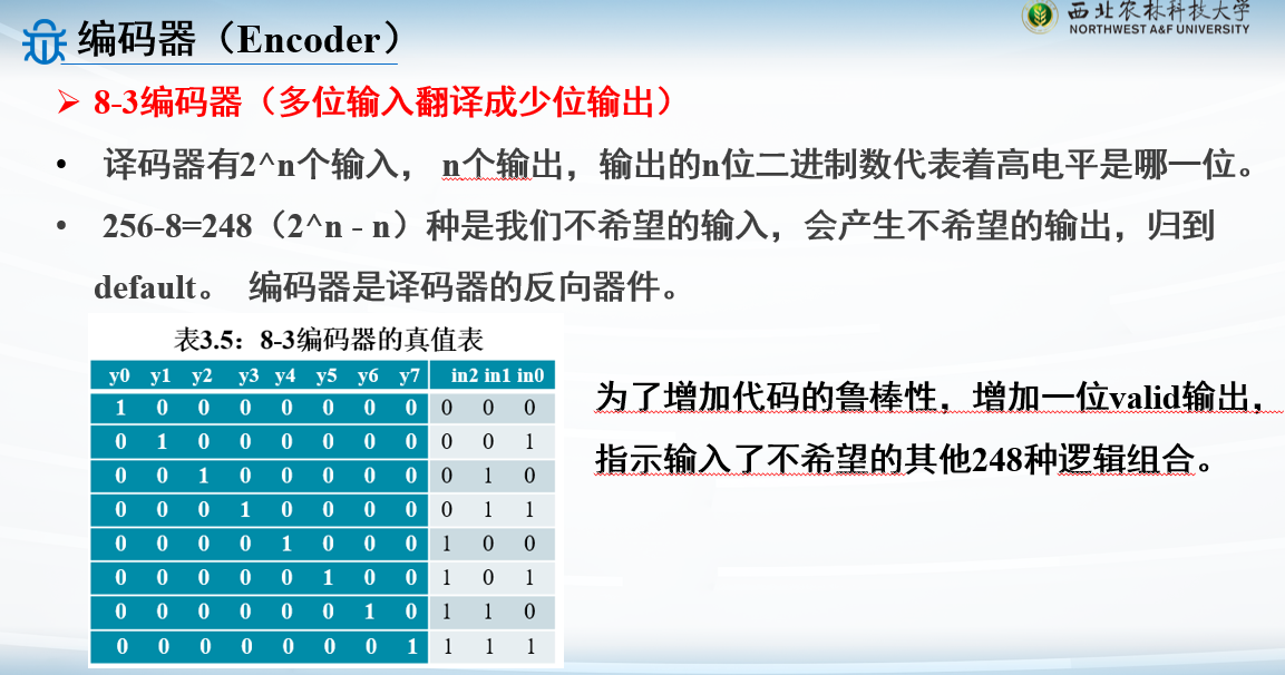
例子:8-3编码器
1
2
3
4
5
6
7
8
9
10
11
12
13
14
15
16
17
18
module Encoder(in,y,valid); input [7 :0 ] in; output reg [2 :0 ] y; output reg valid ; always @* begin valid=1 ; y = 3'b000 ; case (in) 8'b0000_0001 : y=3'b000 ; 8'b0000_0010 : y=3'b001 ; 8'b0000_0100 : y=3'b010 ; 8'b0000_1000 : y=3'b011 ; 8'b0001_0000 : y=3'b100 ; 8'b0010_0000 : y=3'b101 ; 8'b0100_0000 : y=3'b110 ; 8'b1000_0000 : y=3'b111 ; default : valid=0 ; endcase end endmodule
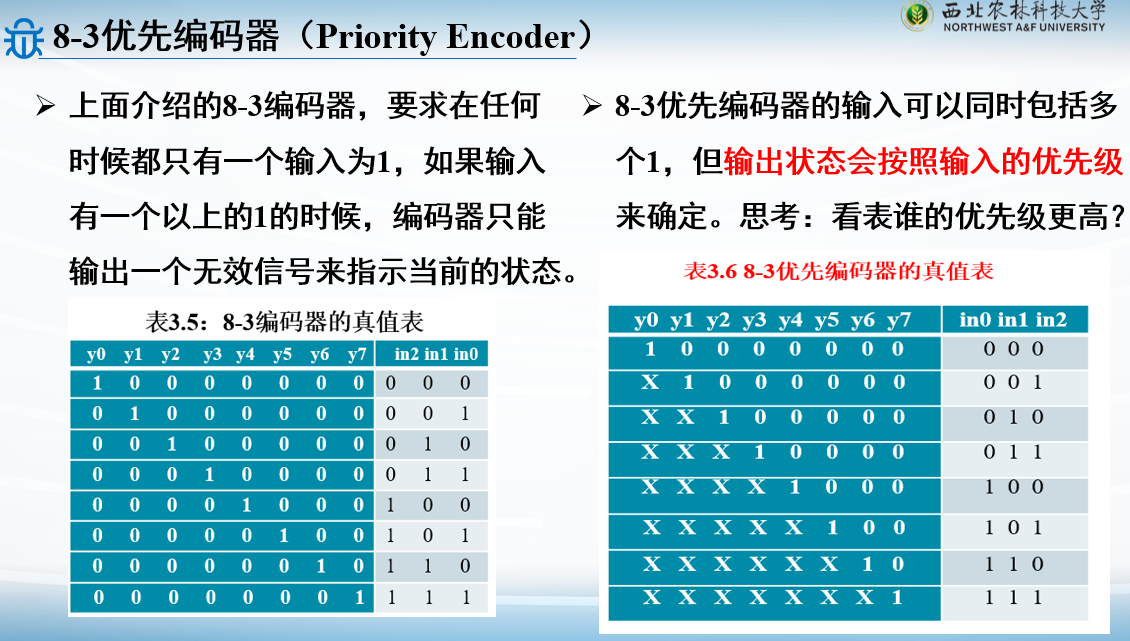
例子:8-3优先编码器
1
2
3
4
5
6
7
8
9
10
11
12
13
14
15
16
module Prio_Encoder(in,y);input [7 :0 ] in;output reg [2 :0 ] y;always @* begin casex (in) 8'b1 ???_????: y=3'b111 ; 8'b01 ??_???? : y=3'b110 ; 8'b001 ?_????: y=3'b101 ; 8'b0001_ ???? : y=3'b100 ; 8'b0000_1 ??? : y=3'b011 ; 8'b0000_01 ??: y=3'b010 ; 8 ’b0000_001?: y=3'b001 ; default : y=3'b000 ; endcase end endmodule
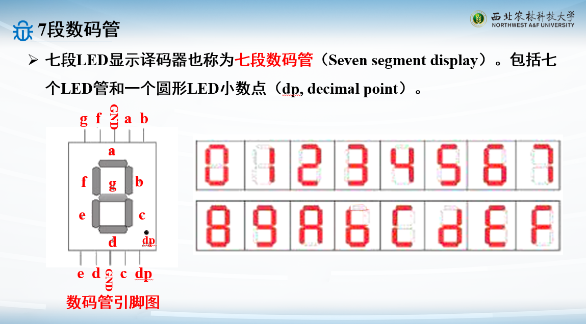
16进制数7段LED显示译码器
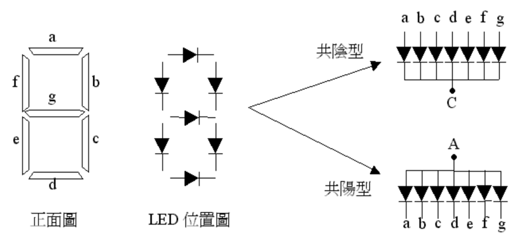
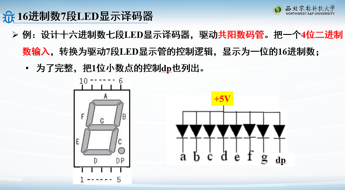
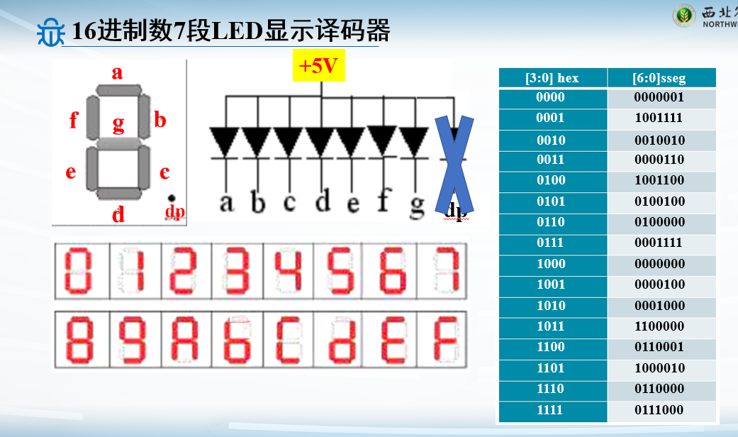
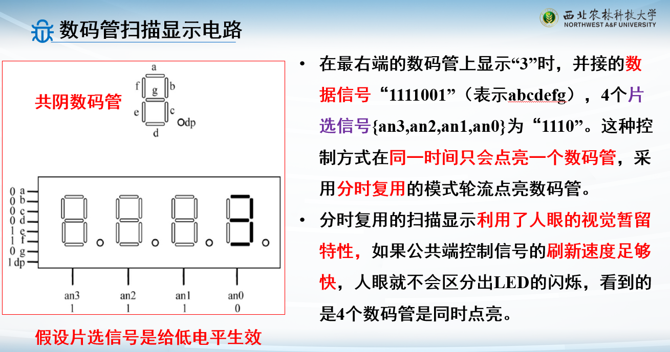
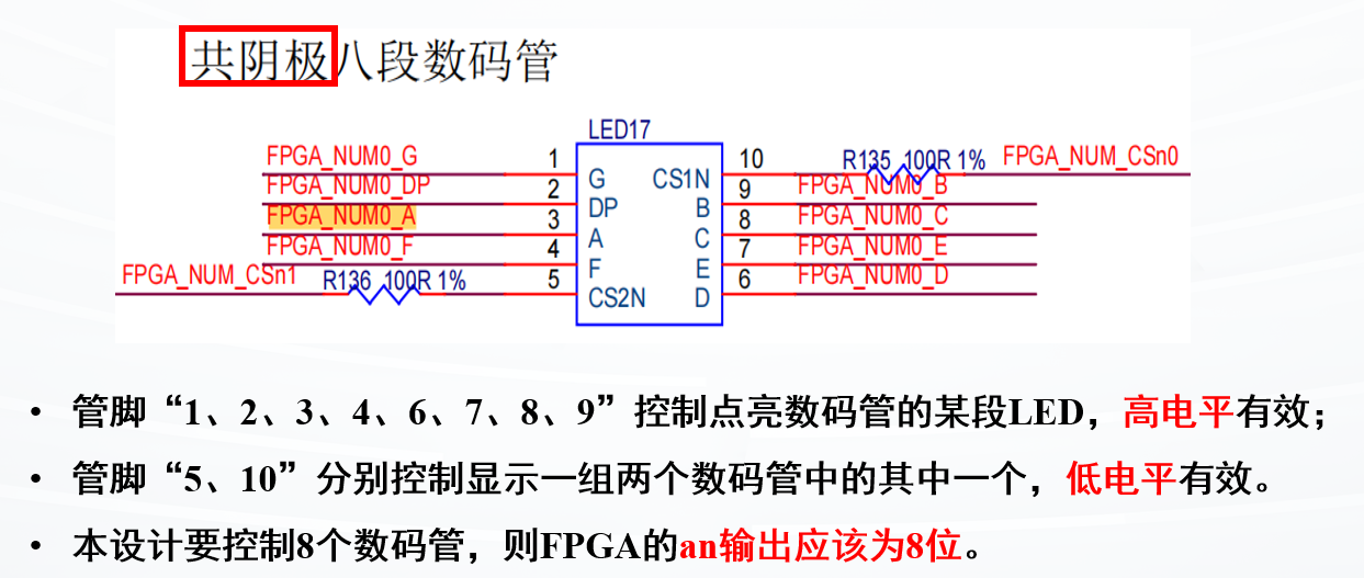
数码管分为共阳极和共阴极
输入是a-g
如果是共阴极,则输入高电平亮
如果是共阳极,则输入低电平亮
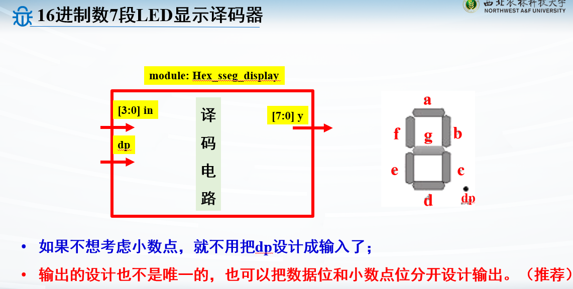
例子:16进制共阳数码管
1
2
3
4
5
6
7
8
9
10
11
12
13
14
15
16
17
18
19
20
21
22
23
24
25
26
module Hex_sseg_display(in,dp,y);input [3 :0 ] in; input dp;output reg [7 :0 ] y; always @* begin y[0 ]=dp; case (in) 4'd0 : y[7 :1 ]=7'b0000001 ; 4'd1 : y[7 :1 ]=7'b1001111 ; 4'd2 : y[7 :1 ]=7'b0010010 ; 4'd3 : y[7 :1 ]=7'b0000110 ; 4'd4 : y[7 :1 ]=7'b1001100 ; 4'd5 : y[7 :1 ]=7'b0100100 ; 4'd6 : y[7 :1 ]=7'b0100000 ; 4'd7 : y[7 :1 ]=7'b0001111 ; 4'd8 : y[7 :1 ]=7'b0000000 ; 4'd9 : y[7 :1 ]=7'b0000100 ; 4'd10 : y[7 :1 ]=7'b0001000 ; 4'd11 : y[7 :1 ]=7'b1100000 ; 4'd12 : y[7 :1 ]=7'b0110001 ; 4'd13 : y[7 :1 ]=7'b1000010 ; 4'd14 : y[7 :1 ]=7'b0110000 ; 4'd15 : y[7 :1 ]=7'b0111000 ; endcase end endmodule
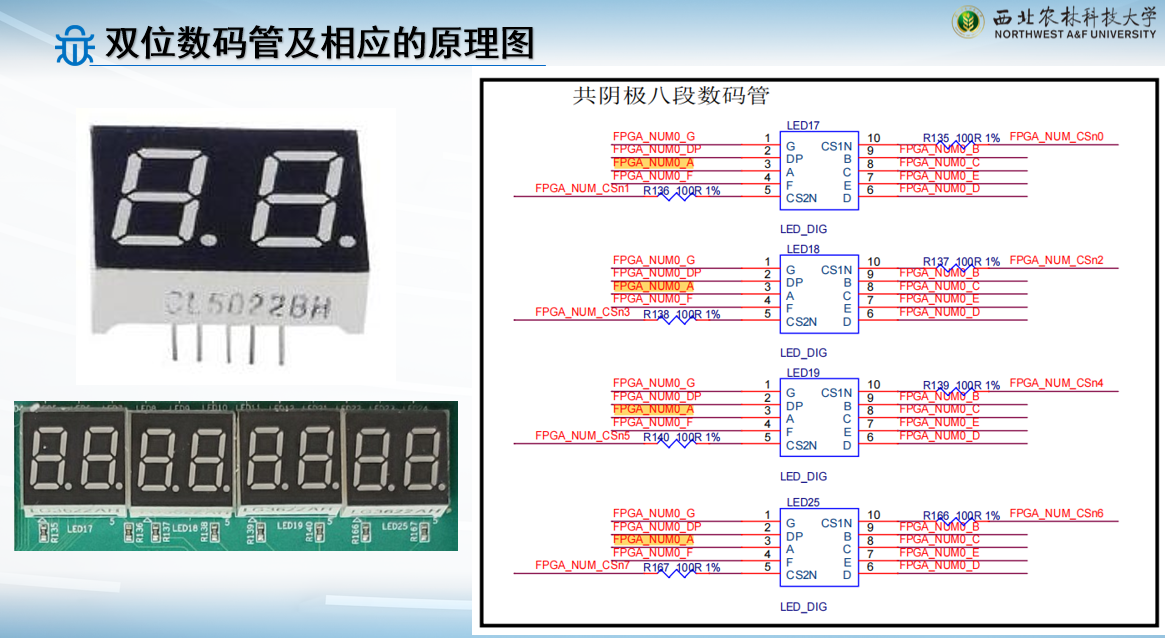
然而实际上我们用到的数码管是多个合在一起的
还会有引脚来选择控制哪个数码管
如果想让一个模块中的两个数码管都点亮,并且显示不同的数字,那么就需要利用人眼的暂留效应 ,对每个要显示的数码管进行动态扫描
即在极短得到时间(小于200ms)内,依次循环显示
时序逻辑电路设计
理解什么是同步异步设计
理解阻塞赋值和非阻塞赋值区别
掌握计数器和秒表 的设计
掌握数码管扫描显示电路 的设计
触发器和锁存器
时序逻辑
数电课程中:根据一个电路是否具有记忆功能 ,可将数字逻辑电路分为组合逻辑电路和时序逻辑电路两种类型
如果一个逻辑电路在任何时刻的稳定输出仅取决于该时刻的输入 ,而与电路过去的输入无关 ,则称组合逻辑电路 (Combinational
Logic Circuit)
如果一个逻辑电路在任何时刻的稳定输出不仅取决于该时刻的输入,而且与过去的输入相关, 则称为时序逻辑电路 (Sequential
Logic Circuit)
时序电路是一种能够记忆电路内部状态的电路
触发器的触发信号常为时钟 或者复位 信号的边沿触发
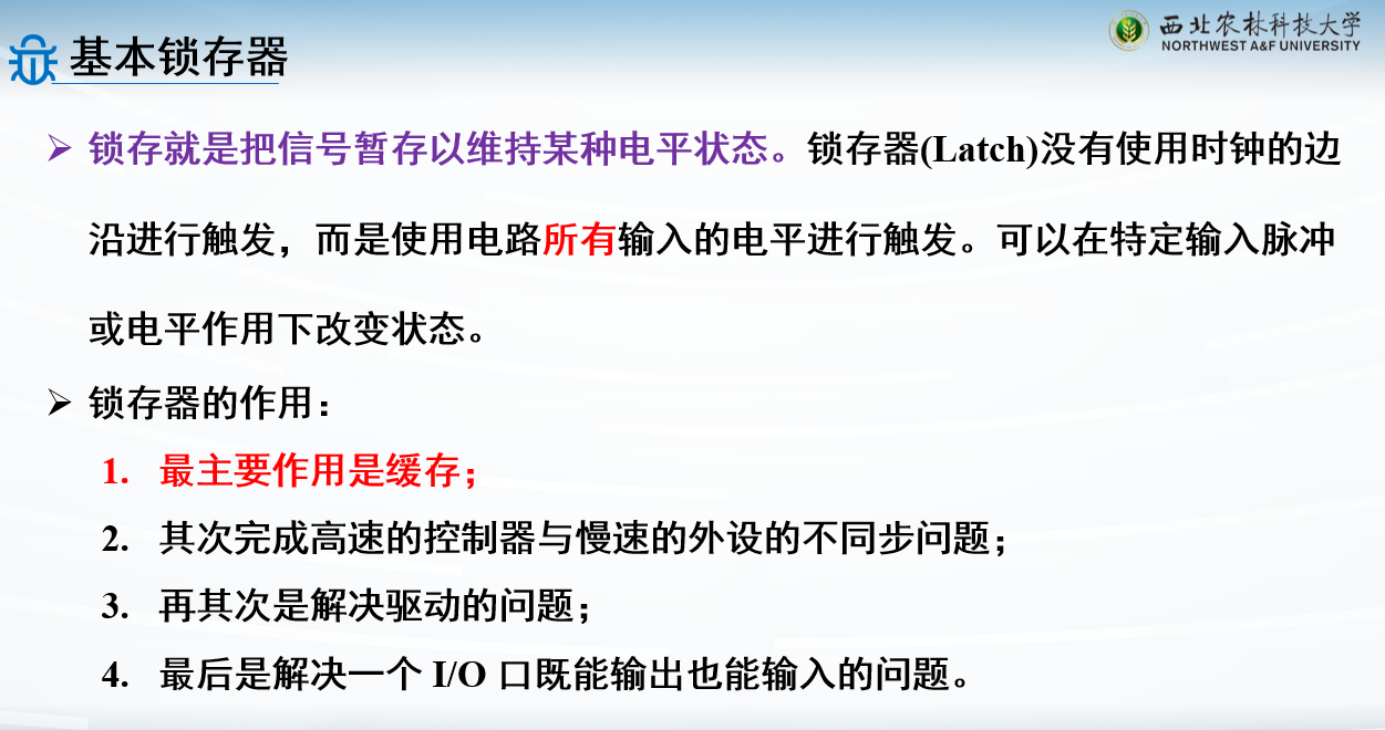
锁存器的触发信号是电平触发
always@ (posedge clk or negedge reset) 或
always@(clk)
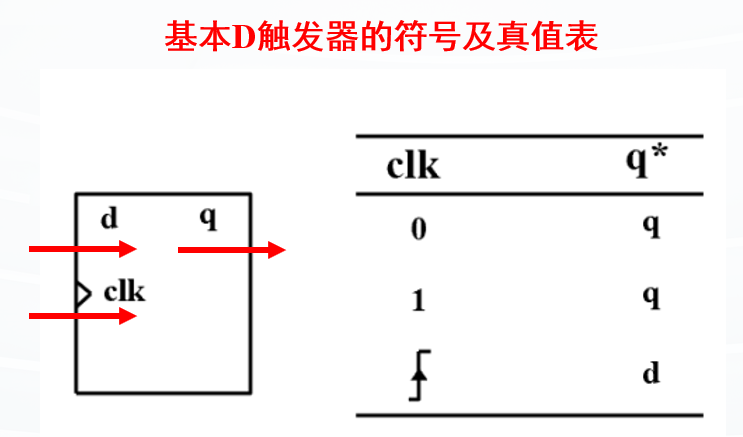
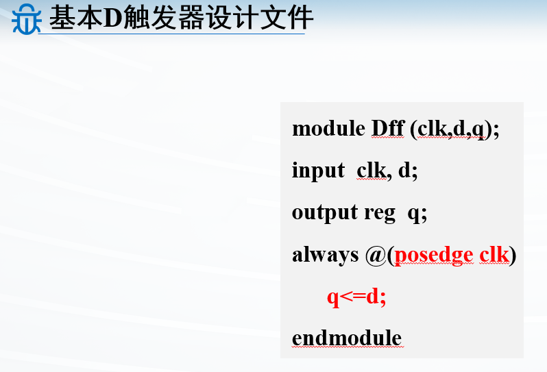
D触发器
D触发器(DFF,D type
Flip-Flop)是时序逻辑电路中最基本的存储元件
上升沿触发(不带异步复位信号)的D触发器是最简单的D触发器
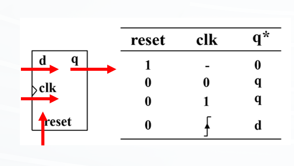
例子:含异步复位的D触发器
D触发器可以包含异步复位信号,同步/异步指的就是是否独立于时钟信号
同步指不独立于时钟信号,被时钟控制
异步指独立于时钟信号
复位信号reset能够在任意时刻复位D触发器,而不受时钟信号控制,不用等时钟边沿
复位信号和时钟信号都写在敏感列表中即是异步复位设计了
敏感信号列表:
1
2
always @(posedge clk or posedge reset ) always @(posedge clk or negedge reset )
reset信号肯定是优先于clk的,所以先判断reset的值
1
2
3
4
5
6
7
8
module Dff_rst(clk, d, reset, q); input d,clk,reset; output reg q; always @(posedge clk or posedge reset) begin if (reset) q<=0 ; else q<=d; end endmodule
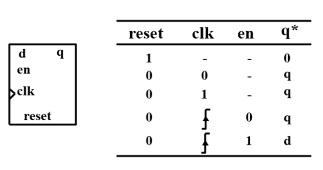
例子:含异步复位和同步使能的D触发器
先判断reset的值
1
2
3
4
5
6
7
8
9
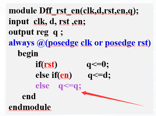
module Dff_rst_en(clk,d,rst,en,q);input clk, d, rst, en;output reg q ;always @(posedge clk or posedge rst) begin if (rst) q<=0 ; else if (en) q<=d; end endmodule
“CE”经常作为“Chip Enable”的缩写
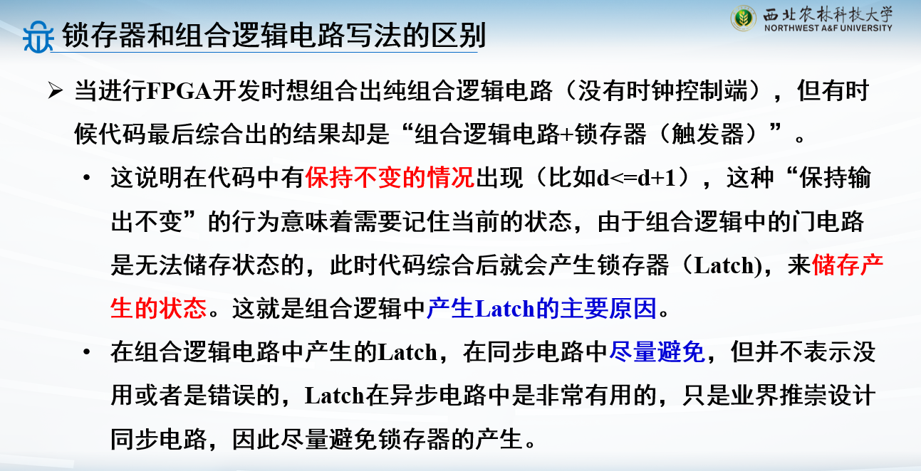
时序逻辑不用考虑所有情况,因为我们需要他产生锁存器
代码中没有描述en=0的行为,则保持先前的值,省略的else分支描述了这个触发器的预期行为
无论写不写省略的else分支,结果都是一样的
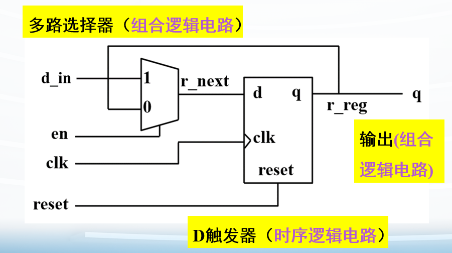
含异步复位和同步使能的D触发器也可以由一个异步复位D触发器和一个多路选择器构成
en输入接到多路选择器
1
2
3
4
5
6
7
8
9
10
11
12
13
14
15
16
module Dff_reset_en (clk,reset,en,d_in,q); input clk,reset,en,d_in;output reg q; reg r_reg, r_next; always @(posedge clk or posedge reset) begin if (reset) r_reg <= 1'b0 ; else r_reg <= r_next; end always @* begin if (en) r_next = d_in; else r_next = r_reg; end always @* q = r_reg; endmodule
同步设计
异步电路设计没有统一的时钟,状态变化的时刻是不稳定的,通常输入信号只在电路处于稳定状态时才发生变化。主要应用于执行系统初始化。例如在打开系统电源之后,可以生成一个短的复位脉冲迫使系统进入初始状态
同步电路设计其所有操作都是在严格的时钟控制下完成的。所有的状态变化都是在时钟的上升沿(或下降沿)完成的
时序逻辑电路设计中非必须情况下不建议使用异步设计
1
2
3
always @(posedge clk) if (rst) q<=1 ’b0; else q<=d;
如果把复位信号写到时钟always里,就是同步复位了
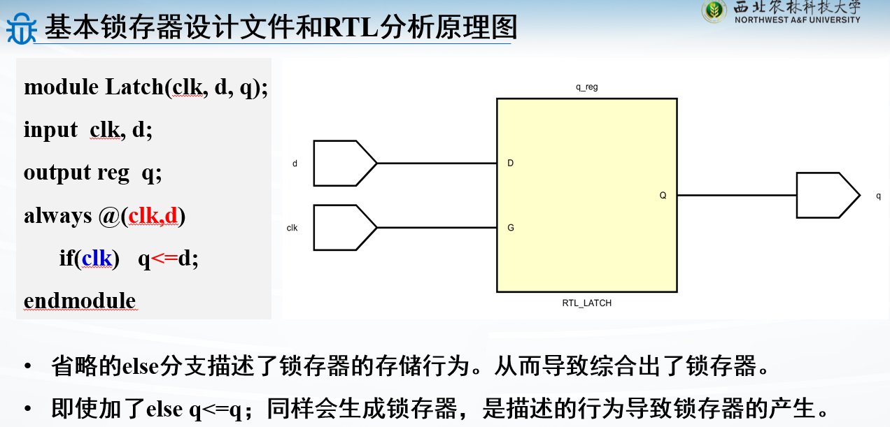
基本锁存器
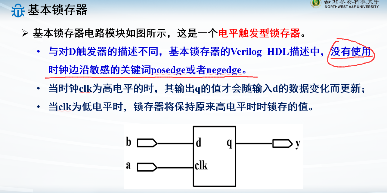
注意:锁存器是用时钟高电平的,并不是时钟边缘 ,所以后面always块的敏感信号就是always @(clk),而不是刚刚D触发器写过的posedge clk或posedge clk
解决锁存器说到底还是分支和初值
写法区别
含清零控制的锁存器
1
2
3
4
5
6
7
8
9
module Latch(clk, d, rst,q);input clk, d, rst;output reg q ; always @(clk,d,rst) if (!rst) q<=0 ; else if (clk) q<=d; endmodule
锁存器和触发器的区别
最主要的区别就是:触发器是时钟边沿触发,锁存器是电平触发
但是能用触发器就用触发器
寄存器
通常把能够用来存储一组二进制信息 的同步时序逻辑电路称为寄存器。常用触发器的边沿触发型
寄存器是构成时序逻辑最重要的一个单元,可以说没有寄存器就没有时序逻辑。寄存器是由触发器组成的,一个触发器可以组成一个一位的寄存器,多个触发器可以组成一个多位的寄存器
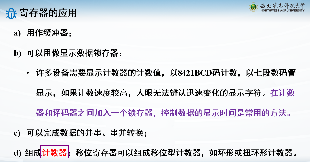
寄存器作用
缓冲,串并转换,计数器,显示数据锁存器
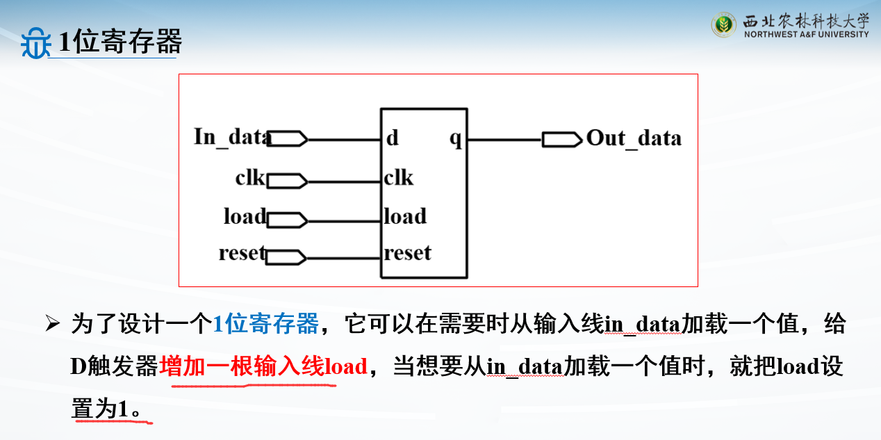
例子:1位寄存器
1
2
3
4
5
6
7
8
9
module reg_1(In_data, clk, load, reset, Out_data); input In_data,clk,load,reset; output Out_data; always @(posedge clk or posedge reset) begin if (reset) Out_data <= 0 ; else if (load) Out_data <= In_data; end endmodule
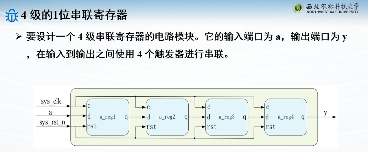
例子:4级的1位串联寄存器
1
2
3
4
5
6
7
8
9
10
11
12
13
14
15
16
17
18
19
20
21
22
23
24
25
26
27
28
29
module shfit_reg( input sys_clk, input sys_rst_n, input a, output y ); reg a_reg1; reg a_reg2; reg a_reg3; reg a_reg4; always @(posedge sys_clk or negedge sys_rst_n) begin if (!sys_rst_n)begin a_reg1 <= 1'b0 ; a_reg2 <= 1'b0 ; a_reg3 <= 1'b0 ; a_reg4 <= 1'b0 ; end else begin a_reg1 <= a; a_reg2 <= a_reg1; a_reg3 <= a_reg2; a_reg4 <= a_reg3; end end assign y = a_reg4;endmodule
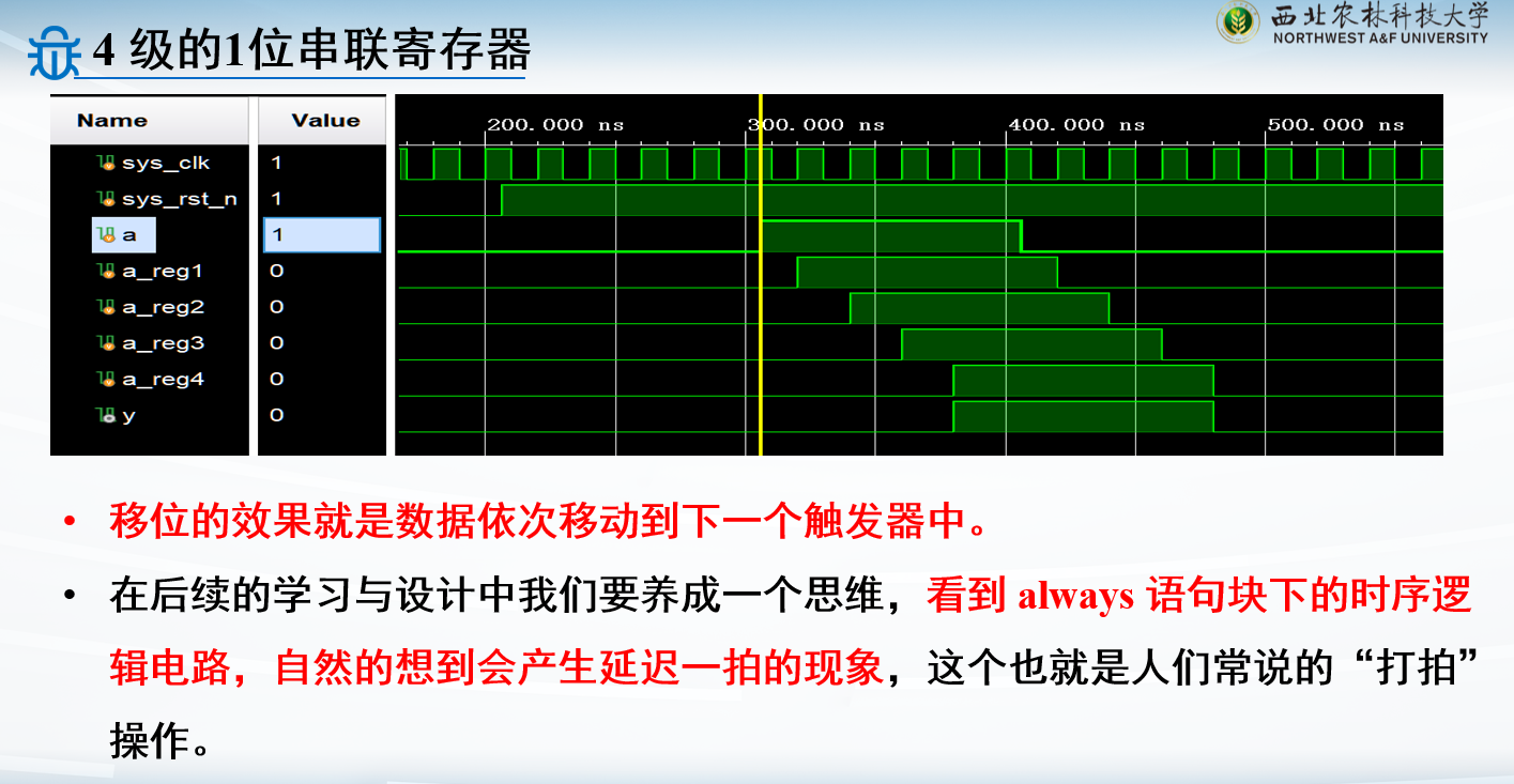
对应的testbench
1
2
3
4
5
6
7
8
9
10
11
12
13
14
15
16
17
18
19
20
21
22
23
24
25
26
27
module tb_shfit_reg(); reg sys_clk;reg sys_rst_n;reg a; wire y; initial begin sys_clk = 1'b1 ; sys_rst_n = 1'b0 ; a = 1'b0 ; #206 sys_rst_n = 1'b1 ; #100 a = 1'b1 ; #100 a = 1'b0 ; end always #10 sys_clk = ~sys_clk;shfit_reg shfit_reg_inst( .sys_clk (sys_clk ),.sys_rst_n (sys_rst_n ),.a (a ), .y (y )); endmodule
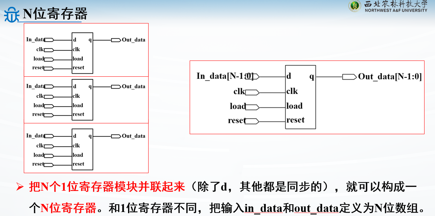
例子:N位寄存器
1
2
3
4
5
6
7
8
9
module reg_N #( parameter N=8) (clk,rst,load,in_data,out_data); input clk, rst,load;input [N-1 :0 ] in_data;output reg [N-1 :0 ] out_data;always @(posedge clk or posedge rst) if (rst) out_data <= 0 ; else if (load) out_data <= in_data; endmodule
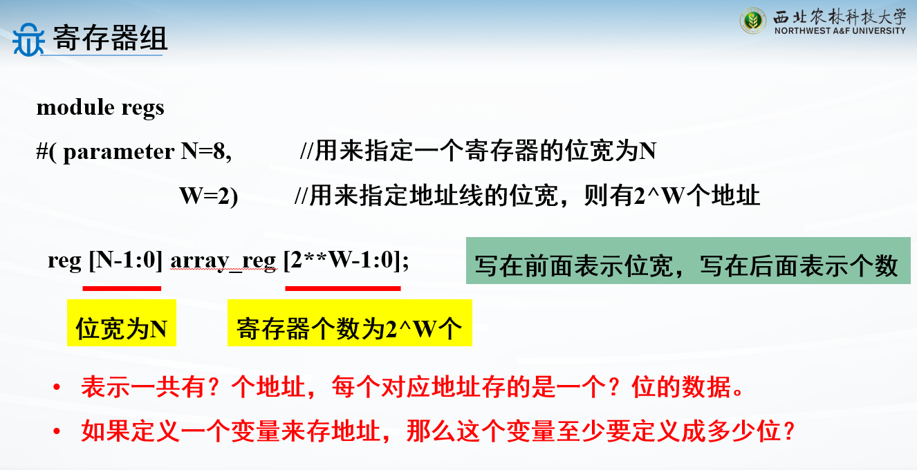
例子:寄存器组
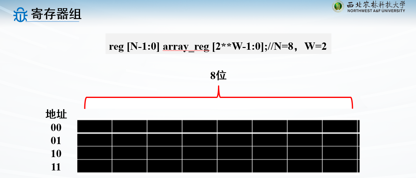
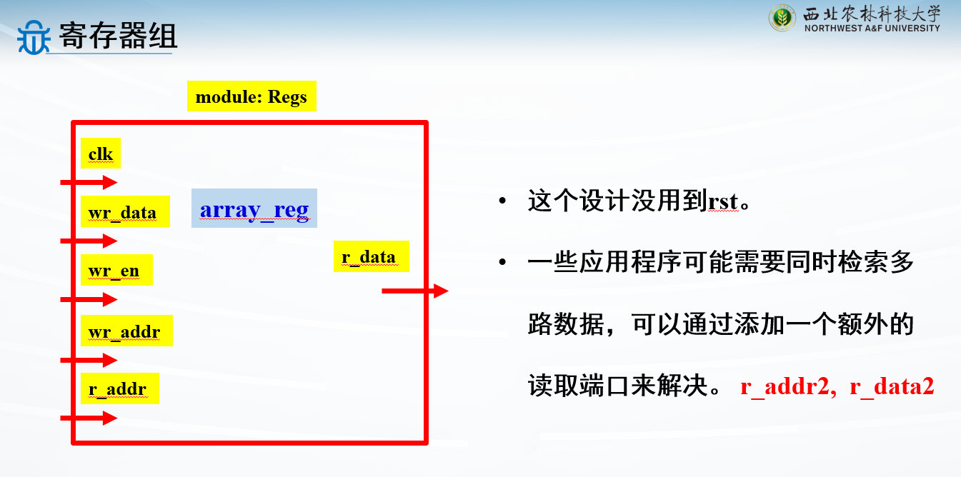
寄存器组是由一组拥有同一个输入端口和一个或多个输出端口的寄存器组成
一共有\(2^W\) 个地址
每一个地址对应\(N\) 位数据
地址线位宽为W,所以变量定义W位
采用了同步写入,异步读出的形式
同步写入,指在时钟信号的控制下写入,体现在代码中就是always @(posedge clk )
异步读出,指随时都能读,体现在代码中就是assign r_data = array_reg[r_addr];
1
2
3
4
5
6
7
8
9
10
11
12
13
14
module Regs #( parameter N=8, W=2) (clk, wr_en, wr_addr, r_addr, wr_data, r_data ); input clk, wr_en;input [W-1 :0 ] wr_addr, r_addr;input [N-1 :0 ] wr_data;output [N-1 :0 ] r_data;reg [N-1 :0 ] array_reg [2 **W-1 :0 ];always @(posedge clk ) if (wr_en) array_reg[wr_addr] <= wr_data; assign r_data=array_reg[r_addr];endmodule
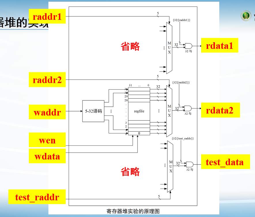
例子:寄存器堆
图一乐就行
1 2 3 4 5 6 7 8 9 10 11 12 13 14 15 16 17 18 19 20 21 22 23 24 25 26 27 28 29 30 31 32 33 34 35 36 37 38 39 40 41 42 43 44 45 46 47 48 49 50 51 52 53 54 55 56 57 58 59 60 61 62 63 64 65 66 67 68 69 70 71 72 73 74 75 76 77 78 79 80 81 82 83 84 85 86 87 88 89 90 91 92 93 94 95 96 97 98 99 100 101 102 103 104 105 106 107 108 109 110 111 112 113 114 115 116 117 118 119 120 121 122 123 124 125 126 127 128 129 130 131 132 133 134 135 136 137 138 139 `timescale 1ns / 1ps module regfile( input clk, input wen, input [4 :0 ] raddr1, input [4 :0 ] raddr2, input [4 :0 ] waddr, input [31 :0 ] wdata, output reg [31 :0 ] rdata1, output reg [31 :0 ] rdata2, input [4 :0 ] test_addr, output reg [31 :0 ] test_data ); reg [31 :0 ] rf[31 :0 ]; always @(posedge clk) begin if (wen) begin rf[waddr] <= wdata; end end always @(*) begin case (raddr1) 5'd1 : rdata1 <= rf[1 ]; 5'd2 : rdata1 <= rf[2 ]; 5'd3 : rdata1 <= rf[3 ]; 5'd4 : rdata1 <= rf[4 ]; 5'd5 : rdata1 <= rf[5 ]; 5'd6 : rdata1 <= rf[6 ]; 5'd7 : rdata1 <= rf[7 ]; 5'd8 : rdata1 <= rf[8 ]; 5'd9 : rdata1 <= rf[9 ]; 5'd10 : rdata1 <= rf[10 ]; 5'd11 : rdata1 <= rf[11 ]; 5'd12 : rdata1 <= rf[12 ]; 5'd13 : rdata1 <= rf[13 ]; 5'd14 : rdata1 <= rf[14 ]; 5'd15 : rdata1 <= rf[15 ]; 5'd16 : rdata1 <= rf[16 ]; 5'd17 : rdata1 <= rf[17 ]; 5'd18 : rdata1 <= rf[18 ]; 5'd19 : rdata1 <= rf[19 ]; 5'd20 : rdata1 <= rf[20 ]; 5'd21 : rdata1 <= rf[21 ]; 5'd22 : rdata1 <= rf[22 ]; 5'd23 : rdata1 <= rf[23 ]; 5'd24 : rdata1 <= rf[24 ]; 5'd25 : rdata1 <= rf[25 ]; 5'd26 : rdata1 <= rf[26 ]; 5'd27 : rdata1 <= rf[27 ]; 5'd28 : rdata1 <= rf[28 ]; 5'd29 : rdata1 <= rf[29 ]; 5'd30 : rdata1 <= rf[30 ]; 5'd31 : rdata1 <= rf[31 ]; default : rdata1 <= 32'd0 ; endcase end always @(*) begin case (raddr2) 5'd1 : rdata2 <= rf[1 ]; 5'd2 : rdata2 <= rf[2 ]; 5'd3 : rdata2 <= rf[3 ]; 5'd4 : rdata2 <= rf[4 ]; 5'd5 : rdata2 <= rf[5 ]; 5'd6 : rdata2 <= rf[6 ]; 5'd7 : rdata2 <= rf[7 ]; 5'd8 : rdata2 <= rf[8 ]; 5'd9 : rdata2 <= rf[9 ]; 5'd10 : rdata2 <= rf[10 ]; 5'd11 : rdata2 <= rf[11 ]; 5'd12 : rdata2 <= rf[12 ]; 5'd13 : rdata2 <= rf[13 ]; 5'd14 : rdata2 <= rf[14 ]; 5'd15 : rdata2 <= rf[15 ]; 5'd16 : rdata2 <= rf[16 ]; 5'd17 : rdata2 <= rf[17 ]; 5'd18 : rdata2 <= rf[18 ]; 5'd19 : rdata2 <= rf[19 ]; 5'd20 : rdata2 <= rf[20 ]; 5'd21 : rdata2 <= rf[21 ]; 5'd22 : rdata2 <= rf[22 ]; 5'd23 : rdata2 <= rf[23 ]; 5'd24 : rdata2 <= rf[24 ]; 5'd25 : rdata2 <= rf[25 ]; 5'd26 : rdata2 <= rf[26 ]; 5'd27 : rdata2 <= rf[27 ]; 5'd28 : rdata2 <= rf[28 ]; 5'd29 : rdata2 <= rf[29 ]; 5'd30 : rdata2 <= rf[30 ]; 5'd31 : rdata2 <= rf[31 ]; default : rdata2 <= 32'd0 ; endcase end always @(*) begin case (test_addr) 5'd1 : test_data <= rf[1 ]; 5'd2 : test_data <= rf[2 ]; 5'd3 : test_data <= rf[3 ]; 5'd4 : test_data <= rf[4 ]; 5'd5 : test_data <= rf[5 ]; 5'd6 : test_data <= rf[6 ]; 5'd7 : test_data <= rf[7 ]; 5'd8 : test_data <= rf[8 ]; 5'd9 : test_data <= rf[9 ]; 5'd10 : test_data <= rf[10 ]; 5'd11 : test_data <= rf[11 ]; 5'd12 : test_data <= rf[12 ]; 5'd13 : test_data <= rf[13 ]; 5'd14 : test_data <= rf[14 ]; 5'd15 : test_data <= rf[15 ]; 5'd16 : test_data <= rf[16 ]; 5'd17 : test_data <= rf[17 ]; 5'd18 : test_data <= rf[18 ]; 5'd19 : test_data <= rf[19 ]; 5'd20 : test_data <= rf[20 ]; 5'd21 : test_data <= rf[21 ]; 5'd22 : test_data <= rf[22 ]; 5'd23 : test_data <= rf[23 ]; 5'd24 : test_data <= rf[24 ]; 5'd25 : test_data <= rf[25 ]; 5'd26 : test_data <= rf[26 ]; 5'd27 : test_data <= rf[27 ]; 5'd28 : test_data <= rf[28 ]; 5'd29 : test_data <= rf[29 ]; 5'd30 : test_data <= rf[30 ]; 5'd31 : test_data <= rf[31 ]; default : test_data <= 32'd0 ; endcase end endmodule
移位寄存器
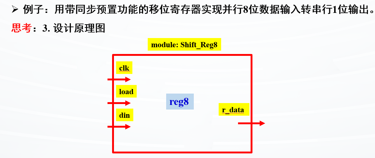
例子:具有同步预置功能的8位移位寄存器
1
2
3
4
5
6
7
8
9
10
11
12
13
14
15
16
17
module Shift_regs(input clk, load,input [7 :0 ] din,output qb ); reg [7 :0 ] reg8;always @(posedge clk ) if (load) reg8 <= din; else reg8[6 :0 ] <= reg8[7 :1 ]; assign qb = reg8[0 ];endmodule
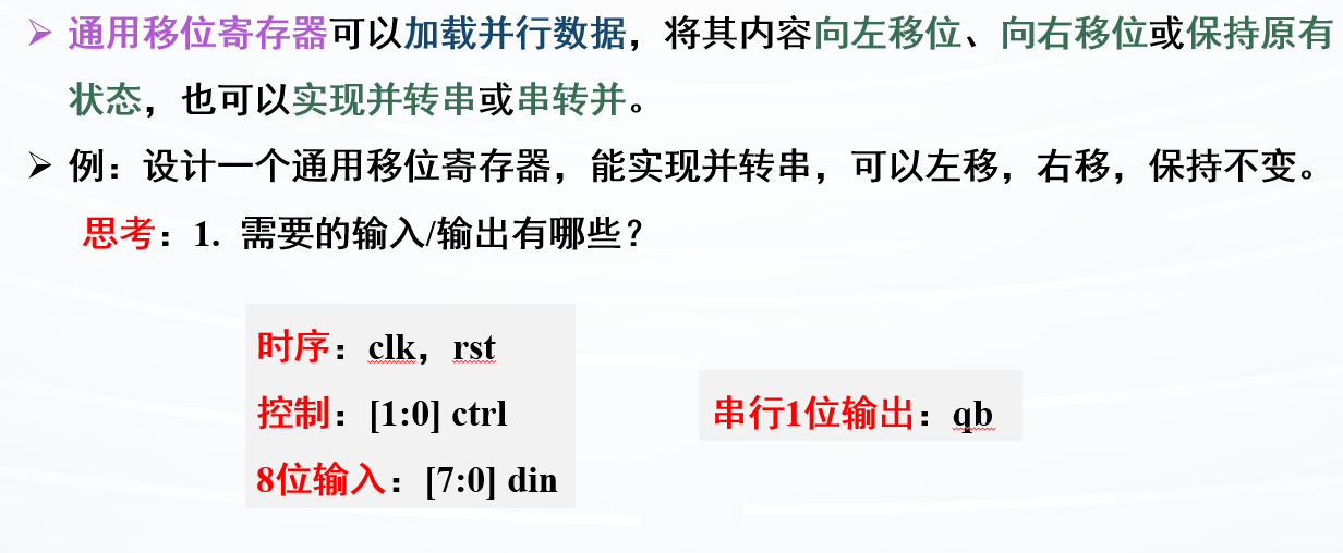
例子:8位通用移位寄存器
循环位移
1
2
3
4
5
6
7
8
9
10
11
12
13
14
15
16
17
18
19
20
21
22
23
24
25
26
27
module Univ_shift_reg #(parameter N=8 ) (input clk, rst,input [1 :0 ] ctrl,input [N-1 :0 ] din,output qb); reg [N-1 :0 ] cs, nst; always @(posedge clk or negedge rst ) if (!rst) cs <= 0 ; else cs <= nst; always @* case (ctrl) 2 ’b00: nst = cs; 2 ’b01: nst = {cs[N-2 :0 ],din[0 ]}; 2 ’b10: nst = {din[N-1 ],cs[N-1 :1 ]}; default : nst = din; endcase assign qb = cs[0 ];endmodule
计数器
很重要
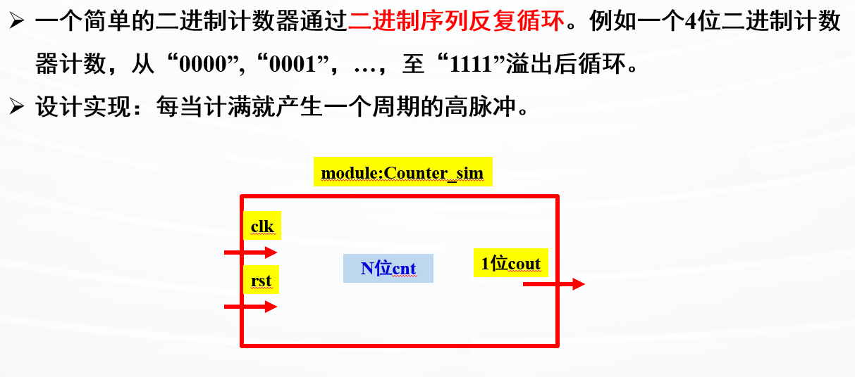
例子:简单的二进制计数器
1
2
3
4
5
6
7
8
9
10
11
12
module Counter_sim #(parameter N=4 ) (clk, rst, cout); input clk, rst; output cout; reg [N-1 :0 ] cnt; always @(posedge clk) begin if (rst) cnt <= 0 ; else cnt <= cnt + 1 ; end assign cout = (cnt==2 **N - 1 )?1 :0 ; endmodule
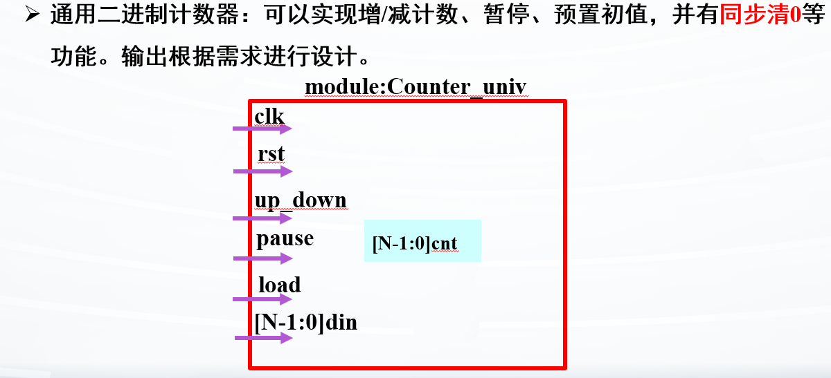
例子:通用的二进制计数器
可以再接一个cout输出
1
2
3
4
5
6
7
8
9
10
11
12
13
14
15
module Counter_univ #(parameter N=4 )(input clk, rst,load,up_down,pause,input [N-1 :0 ] din,output [N-1 :0 ] cout); reg [N-1 :0 ] cnt;always @(posedge clk ) begin if (rst) cnt <= 0 ; else if (load) cnt <= din; else if (pause) cnt <= cnt; else if (up_down) cnt <= cnt + 1 ; else cnt <= cnt - 1 ; end assign cout = cnt;endmodule
例子:模M计数器
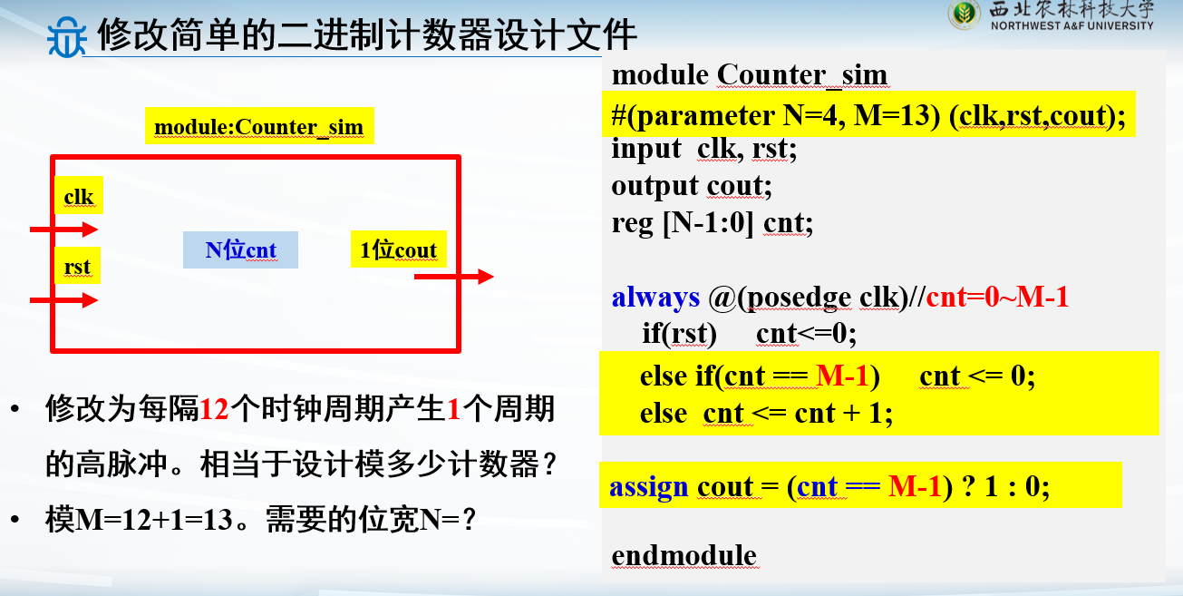
注意运算:每12个周期产生1个周期的高脉冲,则总周期就是12+1=13
1
2
3
4
5
6
7
8
9
10
11
12
13
module Counter_sim #(parameter N=4 , M=13 ) (clk,rst,cout);input clk, rst;output cout;reg [N-1 :0 ] cnt; always @(posedge clk) if (rst) cnt<=0 ; else if (cnt == M-1 ) cnt <= 0 ; else cnt <= cnt + 1 ; assign cout = (cnt == M-1 ) ? 1 : 0 ; endmodule
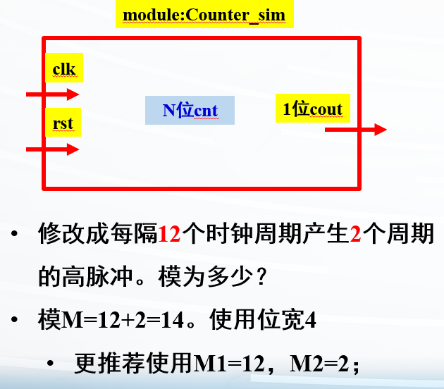
其实不推荐只用一个变量控制周期,因为出现的是两个:一个12,一个1
这个最常用,记住格式即可
1
2
3
4
5
6
7
8
9
10
11
12
module Counter_sim #(parameter N=4 , M1=12 , M2=2 ) (clk,rst,cout); input clk, rst;output cout;reg [N-1 :0 ] cnt; always @(posedge clk) if (rst) cnt <= 0 ; else if (cnt == M1+M2-1 ) cnt <= 0 ; else cnt <= cnt+1 ; assign cout = (cnt < M1) ? 0 : 1 ; endmodule
更推荐这样的写法,一个变量M1控制每间隔的周期,一个变量M2控制产生多少周期的高脉冲
注意这里的输出判断:assign cout = (cnt < M1) ? 0 : 1;
如果计数值没到,就输出0,如果到了,就输出1
这样更好写程序
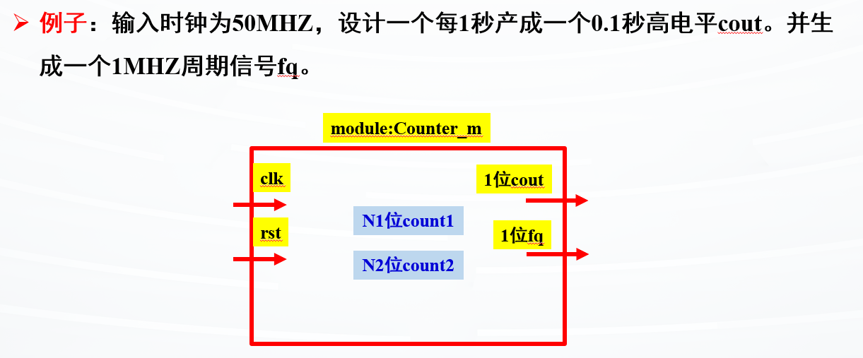
例子:时钟转换
搞清楚对应的时钟周期即可
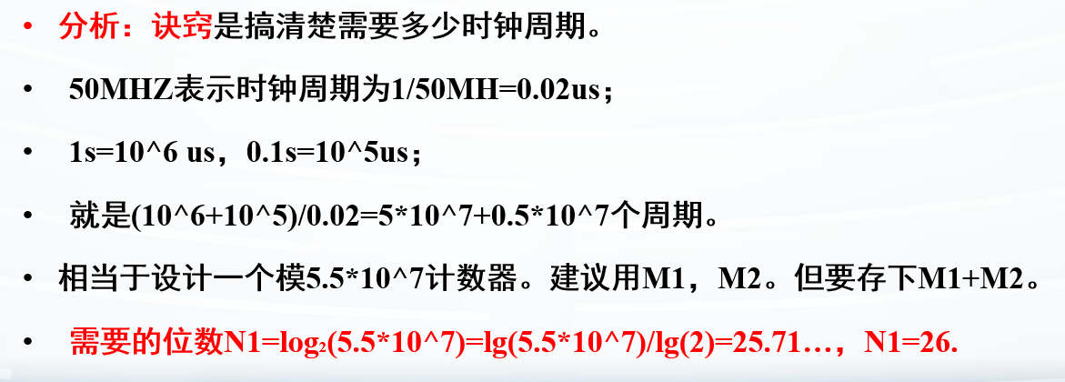
不知道位数就直接设置为32位,肯定能存下
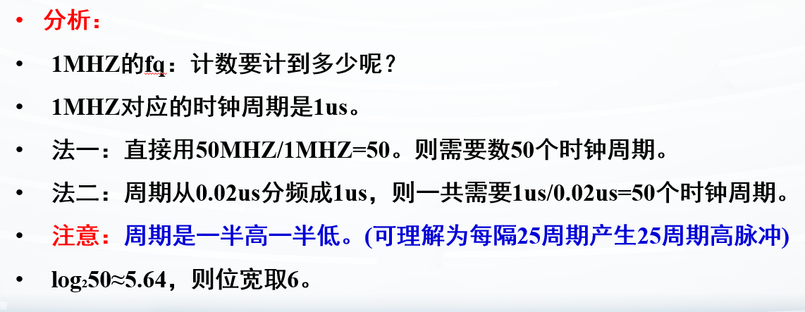
高电平解决了,现在看1MHZ的周期信号
输入信号是50MHZ,即一个时钟周期为\(\dfrac{1}{50\times10^6}=0.02\mu s\)
需要的信号是1MHZ,即一个时钟周期为\(\dfrac{1}{1\times10^6}=1\mu s\)
所以就需要\(\dfrac{1\mu s}{0.02\mu
s}=50\) 个周期
但是需要产生方波,方波是一半一半,则周期再除2,就是每25周期,产生25周期高脉冲
1
2
3
4
5
6
7
8
9
10
11
12
13
14
15
16
17
18
19
20
21
22
23
24
module Counter_m #(parameter M1 = 5 *10 **7 ,M2 = 5 *10 **6 ,M3 = 25 , M4 = 25 ) (clk, rst, cout, fq); input clk,rst; output cout,fq; reg [31 :0 ] cnt1,cnt2; always @(posedge clk) begin if (rst) cnt1 <= 0 ; else if (cnt1 == M1 + M2 - 1 ) cnt1 <= 0 ; else cnt1 <= cnt1 + 1 ; end always @(posedge clk) begin if (rst) cnt2 <= 0 ; else if (cnt2 == M3 + M4 - 1 ) cnt2 <= 0 ; else cnt2 <= cnt2 + 1 ; end assign cout = (cnt1 < M1)?0 :1 ; assign fq = (cnt2 < M3)?0 :1 ; endmodule
对应的testbench
1 2 3 4 5 6 7 8 9 10 11 12 13 14 15 16 17 18 19 20 21 22 23 `timescale 1ns / 1ps module TB_Counter_m #(parameter N1=26 ,M1=5 *10 **7 , M2=5 *10 **6 ,N3=6 ,M3=50 ); reg clk,rst;wire fq;wire cout; Counter_m #(.N1(N1),.N3(N3),.M1(M1),.M2(M2),.M3(M3)) U_Counter_m (.clk (clk),.rst (rst),.fq (fq),.cout (cout)); initial begin rst=0 ; #2 rst=1 ; #2 rst=0 ; end initial begin clk=0 ; forever #1 clk=~clk; end initial #100000000 $finish ; endmodule
输出也可以用时序逻辑输出
1
2
3
4
5
6
7
8
9
10
11
12
13
14
15
16
17
18
19
20
21
22
23
24
25
26
27
28
29
30
31
module Counter_m #(parameter N1=26 ,M1=5 *10 **7 , M2=5 *10 **6 ,N3=6 ,M3=50 )( input clk, rst, output reg cout,fq ); reg [N1-1 :0 ] count1; reg [N3-1 :0 ] count2; always @(posedge clk) if (rst) count1 <= 0 ; else if (count1 == M1+M2-1 ) count1 <= 0 ; else count1 <= count1 + 1 ; always @(posedge clk) if (rst) count2 <= 0 ; else if (count2 == M3-1 ) count2 <= 0 ; else count2 <= count2+1 ; always @(posedge clk) if (rst) cout <= 0 ; else if (count1 >= M1-1 & count1 < M1+M2-1 ) cout <= 1 ; else cout <= 0 ; always @(posedge clk) if (rst) fq <= 0 ; else if (count2 >= M3/2 -1 & count2 < M3-1 ) fq <= 1 ; else fq <= 0 ; endmodule
不推荐,还是推荐刚刚的写法,很固定,很好记
时序逻辑电路设计
例子:按键边沿检测电路设计
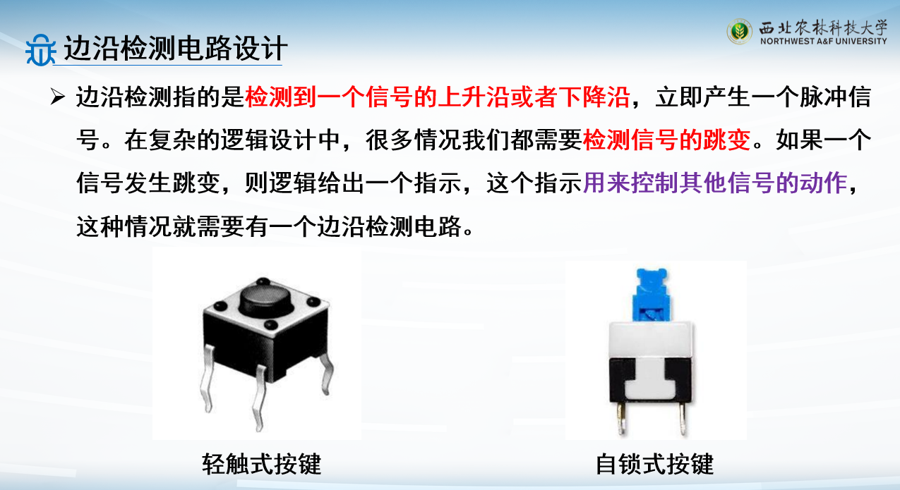
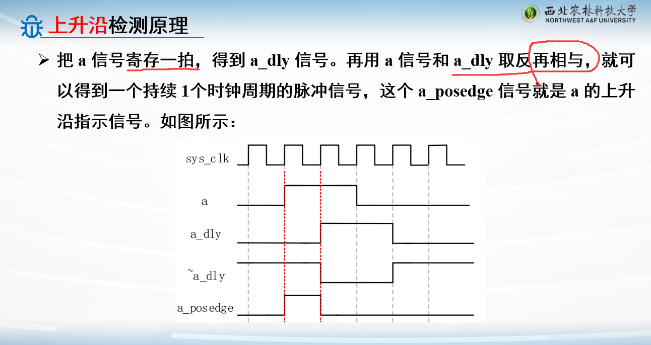
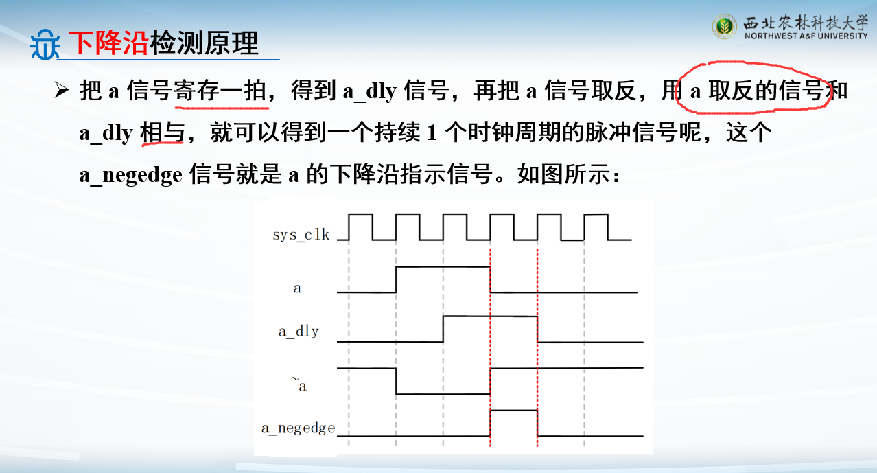
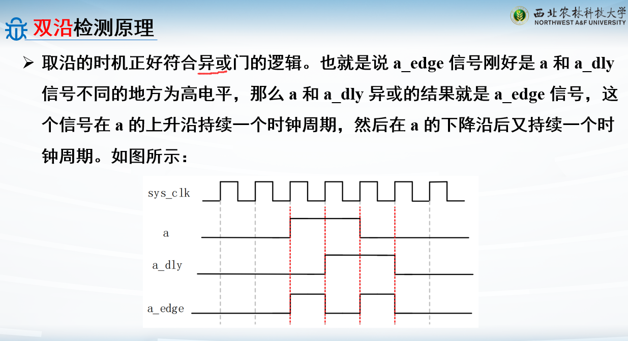
边沿检测电路根据检测边沿的类型一般分为上升沿检测电路 、下降沿检测电路 和双沿检测电路
delay信号:用一个寄存器就行
上升沿:
下降沿:
双沿:
1
2
3
4
5
6
7
8
9
10
11
12
13
14
15
16
17
18
19
20
21
22
23
module edge_test( input sys_clk , input sys_rst_n , input a , output a_posedge , output a_negedge , output a_edge); reg a_dly; always @(posedge sys_clk or negedge sys_rst_n) begin if (!sys_rst_n) a_dly <= 1'b0 ; else a_dly <= a; end assign a_posedge = a & ~a_dly; assign a_negedge = ~a & a_dly; assign a_edge = a ^ a_dly ; endmodule
对应的testbench:
1 2 3 4 5 6 7 8 9 10 11 12 13 14 15 16 17 18 19 20 21 22 23 24 25 26 27 28 29 30 31 32 `timescale 1ns / 1ns module tb_edge_test(); reg sys_clk ; reg sys_rst_n ; reg a ; wire a_posedge ; wire a_negedge ; wire a_edge ; initial begin sys_clk = 1'b1 ; sys_rst_n <= 1'b0 ; a <= 1'b0 ; #201 sys_rst_n <= 1'b1 ; #20 a <= 1'b1 ; #100 a <= 1'b0 ; end always #10 sys_clk <= ~sys_clk; edge_test edge_test_inst( .sys_clk (sys_clk ), .sys_rst_n (sys_rst_n ), .a (a ), .a_posedge (a_posedge ), .a_negedge (a_negedge ), .a_edge (a_edge ) ); endmodule
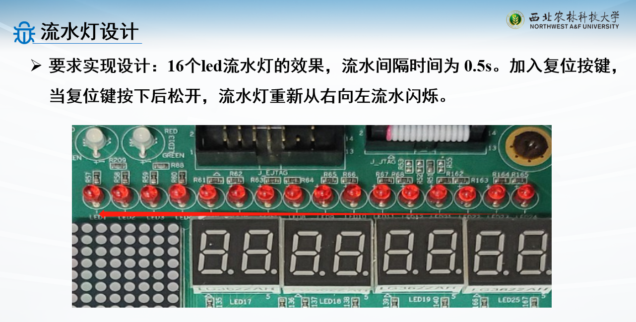
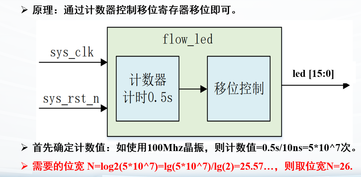
例子:流水灯设计
灯:1灭0亮
1
2
3
4
5
6
7
8
9
10
11
12
13
14
15
16
17
18
19
20
21
22
23
24
25
26
27
module flow_led (sys_clk,sys_rst_n, led); input sys_clk ; input sys_rst_n; output reg [15 :0 ] led ; parameter M=50000000 ;reg [25 :0 ] cnt ; always @(posedge sys_clk or negedge sys_rst_n) begin if (!sys_rst_n) cnt <= 26'd0 ; else if (cnt == (M - 26'd1 )) cnt <= 26'd0 ; else cnt <= cnt + 26'd1 ; end always @(posedge sys_clk or negedge sys_rst_n) begin if (!sys_rst_n) led <= 16'hF_F_F_E ; else if (cnt == (M - 26'd1 )) led <= {led[14 :0 ],led[15 ]}; else led <= led; end endmodule
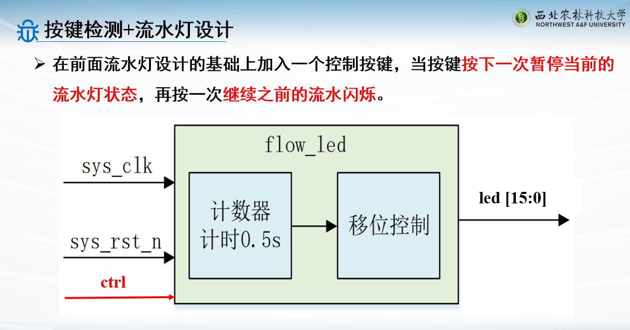
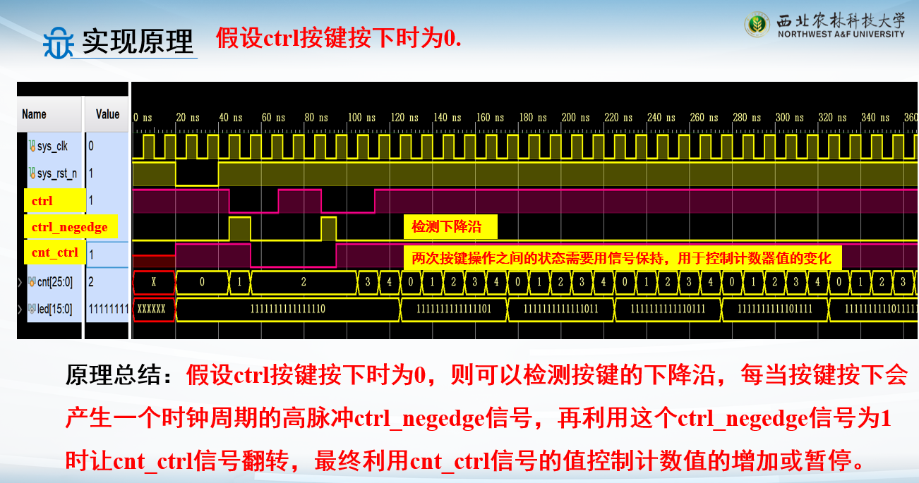
例子:按键检测+流水灯设计
按下按键暂停,再按下按键继续
灯的流动是受计数值控制的!
因此暂停的关键是用控制信号控制住计数器值的变化!
检测到按键下降沿以后,控制计数器不变
再检测到按键下降沿,控制计数器继续计数
1
2
3
4
5
6
7
8
9
10
11
12
13
14
15
16
17
18
19
20
21
22
23
24
25
26
27
28
29
30
31
32
33
34
35
36
37
38
39
40
41
42
43
44
45
46
47
48
49
50
51
52
53
module flow_led (sys_clk,sys_rst_n,ctrl, led); input sys_clk ; input sys_rst_n; input ctrl; output reg [15 :0 ] led ; parameter M=50000000 ;reg [25 :0 ] cnt ; reg cnt_ctrl;wire ctrl_negedge; always @(posedge sys_clk or negedge sys_rst_n) begin if (!sys_rst_n) cnt_ctrl <= 1'd1 ; else if (ctrl_negedge == 1'd1 ) cnt_ctrl <= ~cnt_ctrl; else cnt_ctrl <= cnt_ctrl; end always @(posedge sys_clk or negedge sys_rst_n) begin if (!sys_rst_n) cnt <= 26'd0 ; else if (!cnt_ctrl) cnt <= cnt; else if (cnt == (M - 26'd1 )) cnt <= 26'd0 ; else cnt <= cnt+ 26'd1 ; end always @(posedge sys_clk or negedge sys_rst_n) begin if (!sys_rst_n) led <= 16'hF_F_F_E ; else if (cnt == (M - 26'd1 )) led <= {led[14 :0 ],led[15 ]}; else led <= led; end edge_test u_edge_test( .sys_clk (sys_clk ), .sys_rst_n (sys_rst_n ), .a (ctrl ), .a_negedge (ctrl_negedge ) ); endmodule
就是把上面两种设计结合起来,很容易
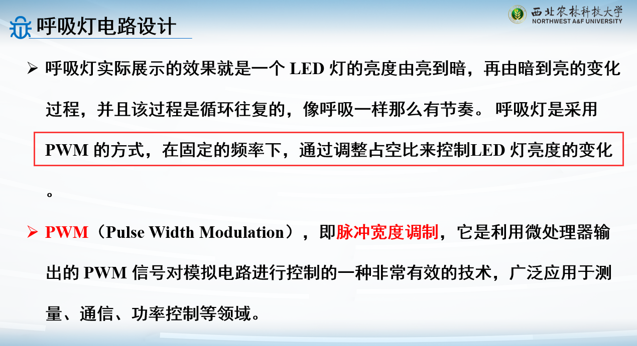
例子:呼吸灯设计
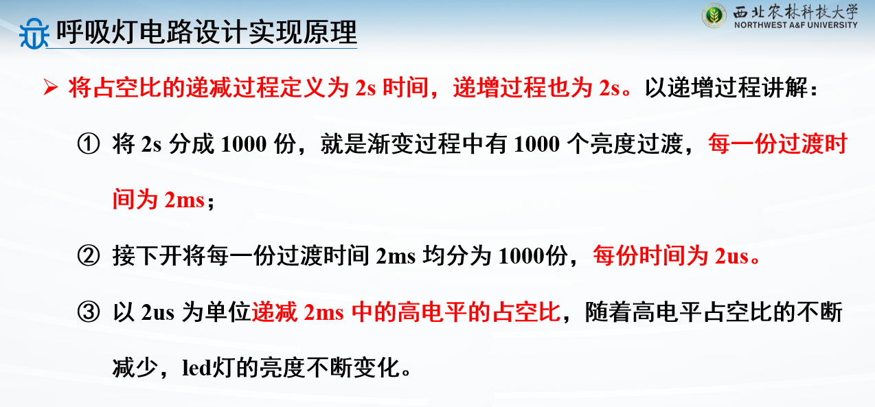
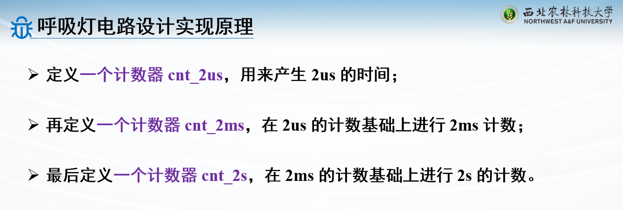
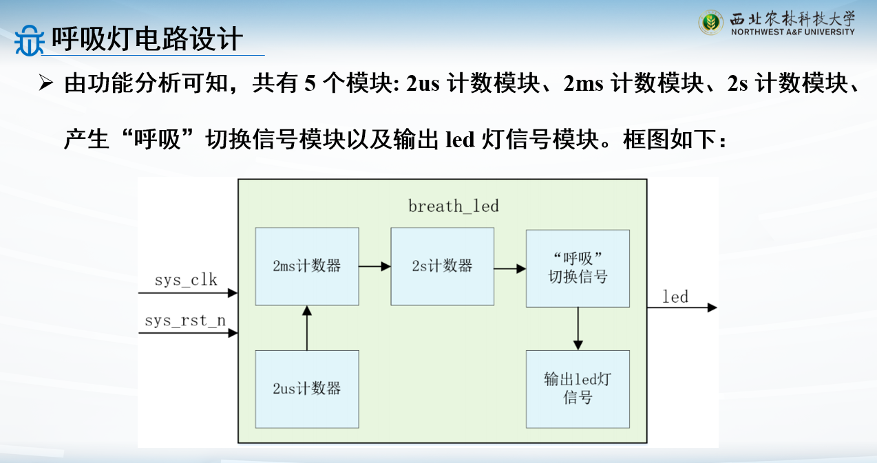
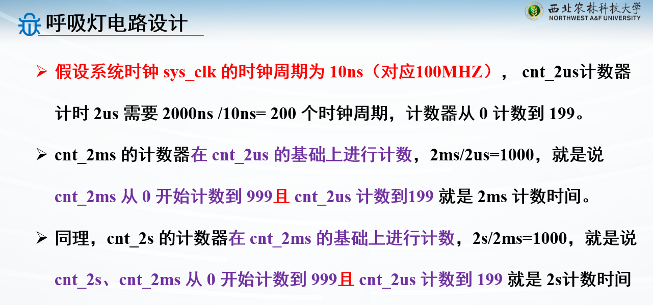
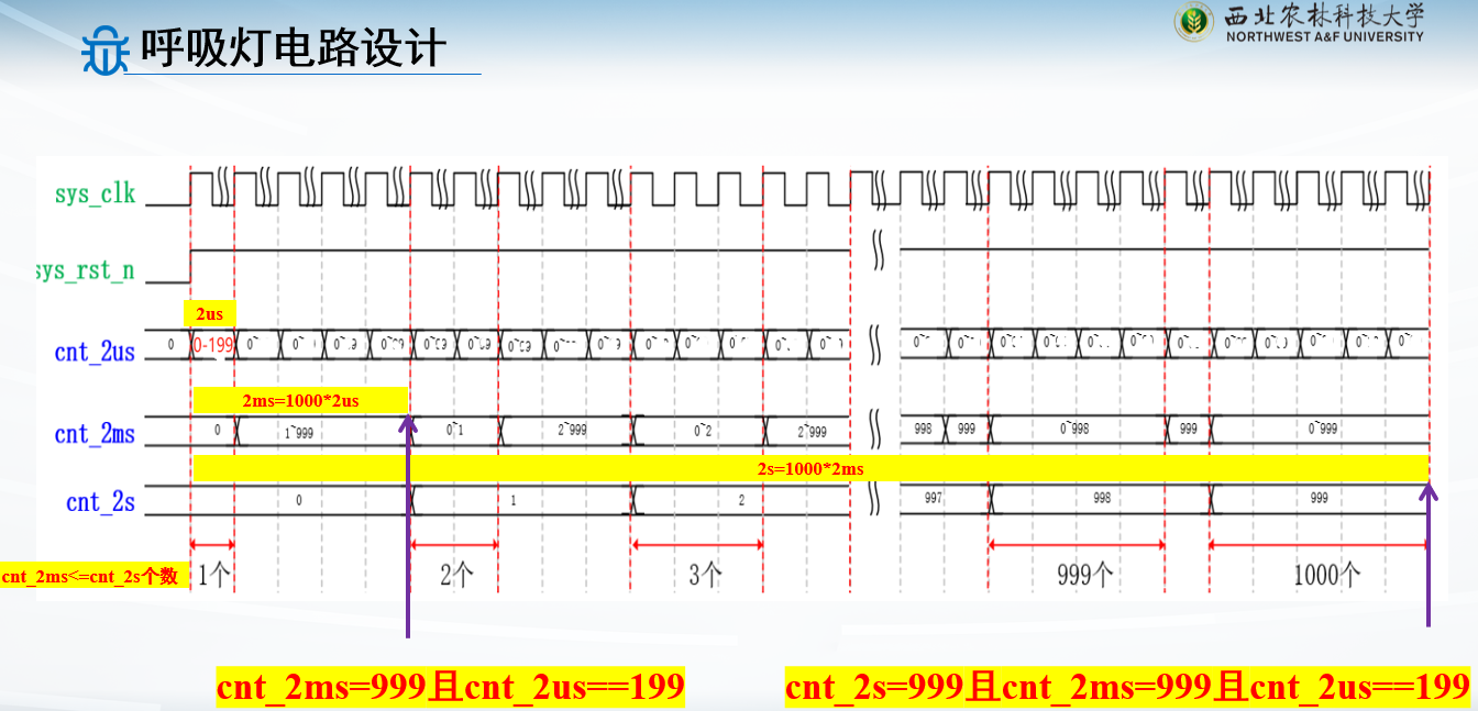
需要三种计数器:
2s,2ms,2us
这里的三个计数器都相互有联系:2ms的计数器用2us控制来自增,2s的计数器用2ms控制来自增
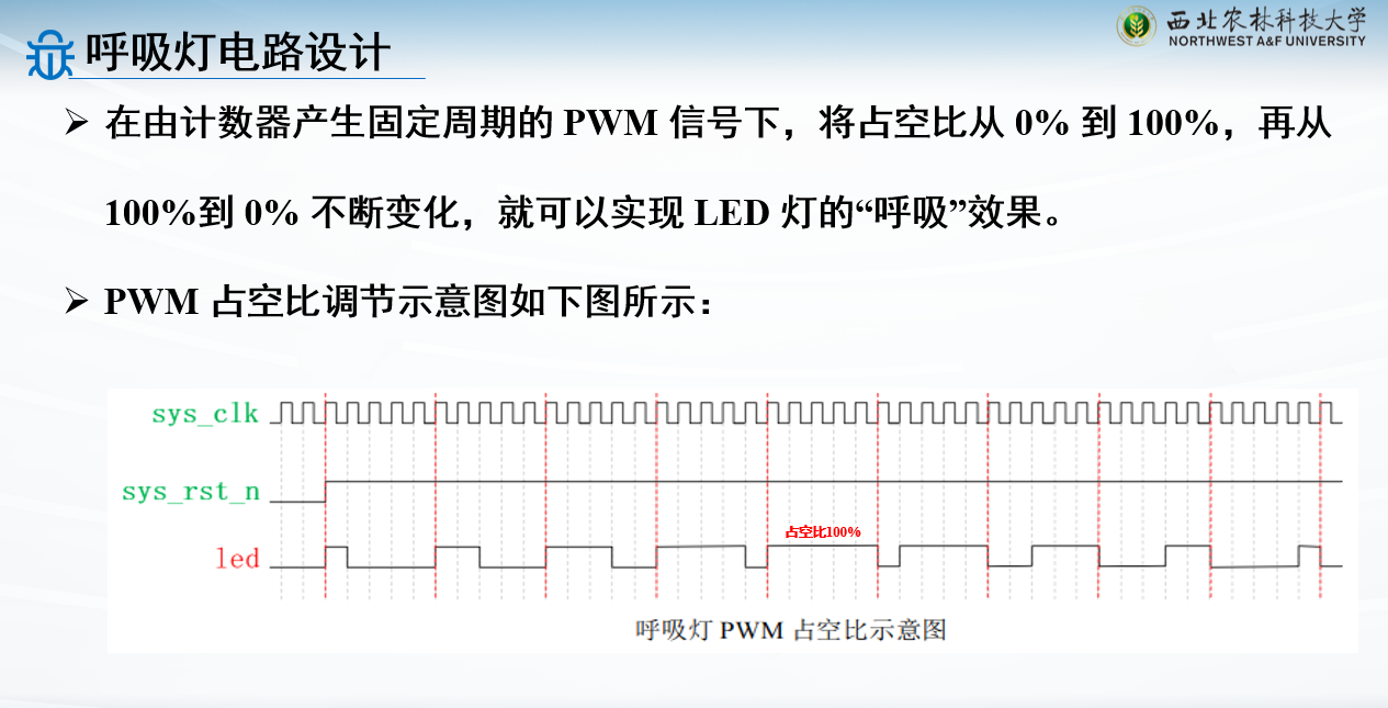
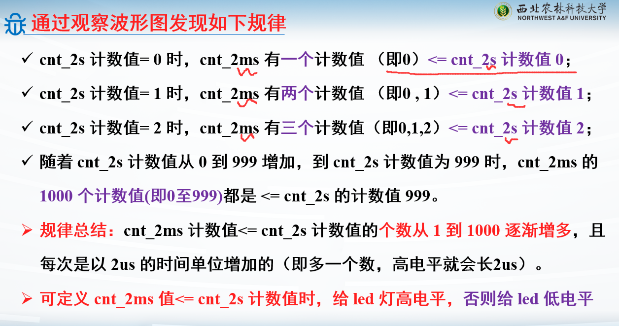
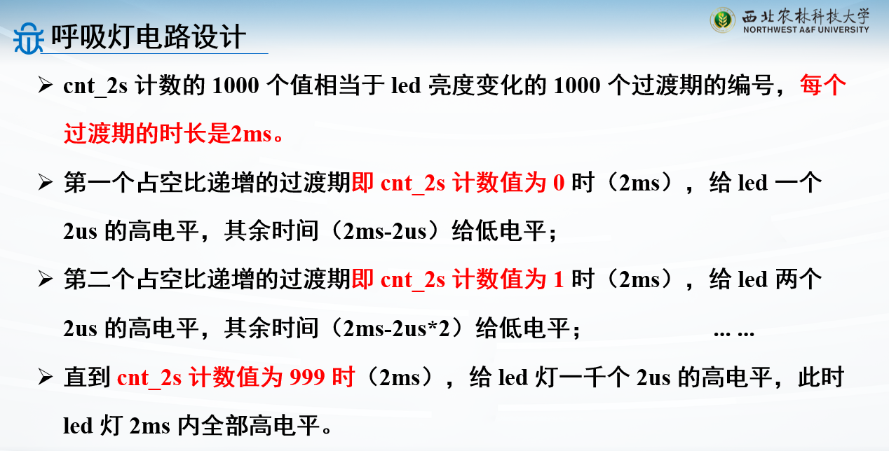
其实也可以三个独立计数,但是这里涉及到“占空比”这个概念
需要改变对应的占空比,才设置成三种相互联系的方式
这张图就可以解释为什么要用三种相互联系
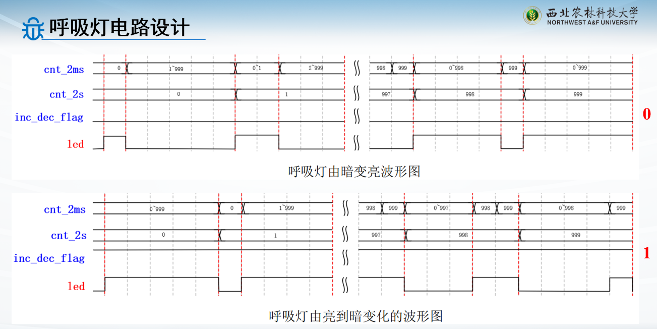
用2ms和2s的计数值作比较:当2ms比2s计数值小的时候,给led高电平,不然就给低电平
可以看到,用三种相互联系的方式,2ms和2s计数值都是0-999,这个比较就很好做;如果用3个计数器独立的方式,就很难设计占空比的控制
1
2
3
4
5
6
7
8
9
10
11
12
13
14
15
16
17
18
19
20
21
22
23
24
25
26
27
28
29
30
31
32
33
34
35
36
37
38
39
40
41
42
43
44
45
46
47
48
49
50
51
52
53
54
55
56
57
58
59
60
61
62
63
64
65
66
67
68
69
70
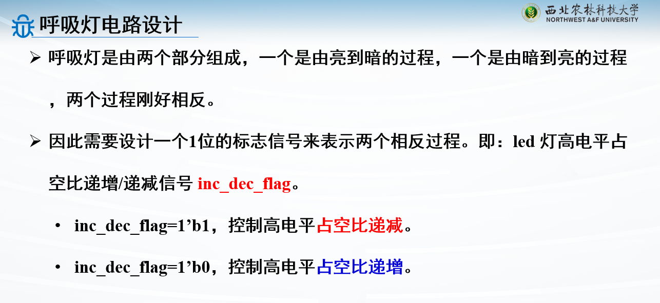
module breath_led( input sys_clk , input sys_rst_n , output reg led ); parameter CNT_2US_MAX = 8'd200 ; parameter CNT_2MS_MAX = 10'd1000 ; parameter CNT_2S_MAX = 10'd1000 ; reg [7 :0 ] cnt_2us; reg [9 :0 ] cnt_2ms; reg [9 :0 ] cnt_2s; reg inc_dec_flag; always @(posedge sys_clk or negedge sys_rst_n) begin if (!sys_rst_n) cnt_2us <= 8'b0 ; else if (cnt_2us == (CNT_2US_MAX - 8'b1 )) cnt_2us <= 8'b0 ; else cnt_2us <= cnt_2us + 8'b1 ; end always @(posedge sys_clk or negedge sys_rst_n) begin if (!sys_rst_n) cnt_2ms <= 10'b0 ; else if (cnt_2ms == (CNT_2MS_MAX - 10'b1 ) && cnt_2us == (CNT_2US_MAX - 8'b1 )) cnt_2ms <= 10'b0 ; else if (cnt_2us == CNT_2US_MAX - 8'b1 ) cnt_2ms <= cnt_2ms + 10'b1 ; else cnt_2ms <= cnt_2ms; end always @(posedge sys_clk or negedge sys_rst_n) begin if (!sys_rst_n) cnt_2s <= 10'b0 ; else if (cnt_2s == (CNT_2S_MAX - 10'b1 ) && cnt_2ms == (CNT_2MS_MAX - 10'b1 ) && cnt_2us == (CNT_2US_MAX - 8'b1 )) cnt_2s <= 10'b0 ; else if (cnt_2ms == (CNT_2MS_MAX - 10'b1 ) && cnt_2us == (CNT_2US_MAX - 8'b1 )) cnt_2s <= cnt_2s + 10'b1 ; else cnt_2s <= cnt_2s; end always @(posedge sys_clk or negedge sys_rst_n) begin if (!sys_rst_n) inc_dec_flag <= 1'b0 ; else if (cnt_2s == (CNT_2S_MAX - 10'b1 ) && cnt_2ms ==( CNT_2MS_MAX - 10'b1 ) && cnt_2us == (CNT_2US_MAX - 8'b1 )) inc_dec_flag <= ~inc_dec_flag; else inc_dec_flag <= inc_dec_flag; end always @(posedge sys_clk or negedge sys_rst_n) begin if (!sys_rst_n) led <= 1'b0 ; else if ((inc_dec_flag == 1'b1 && cnt_2ms >= cnt_2s) || (inc_dec_flag == 1'b0 && cnt_2ms <= cnt_2s)) led <= 1'b1 ; else led <= 1'b0 ; end endmodule
IP核调用
库函数调用
IP核:知识产权核
IP Man:叶问(IP侠)
就挺搞笑的
数码管扫描显示电路
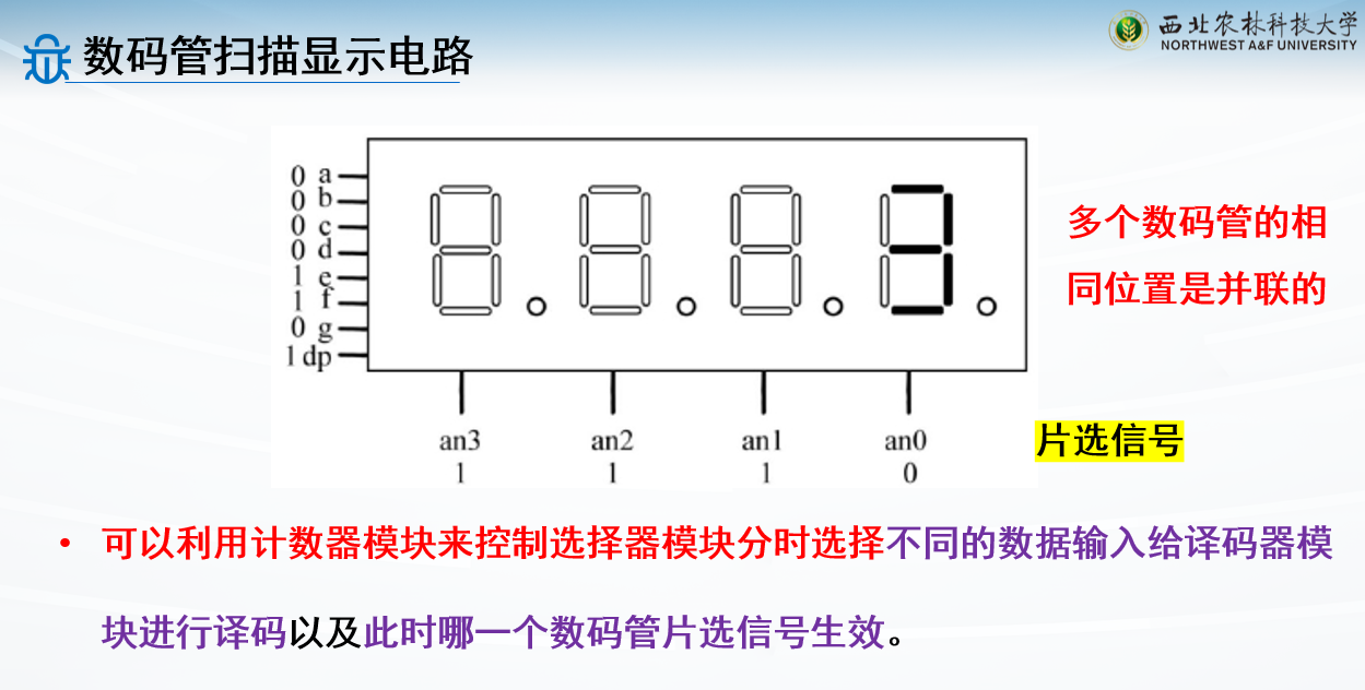
多个数码管:
分时复用即可
利用人眼视觉暂留效应
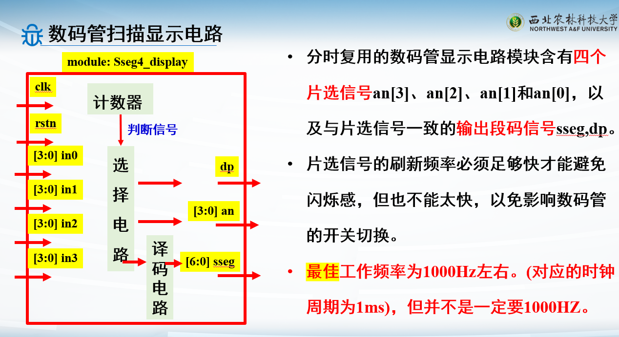
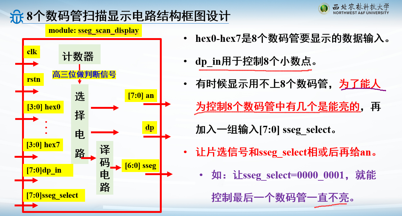
控制信号产生:高位做控制信号,记满就会进位
例子:8个共阴极数码管扫描显示电路设计
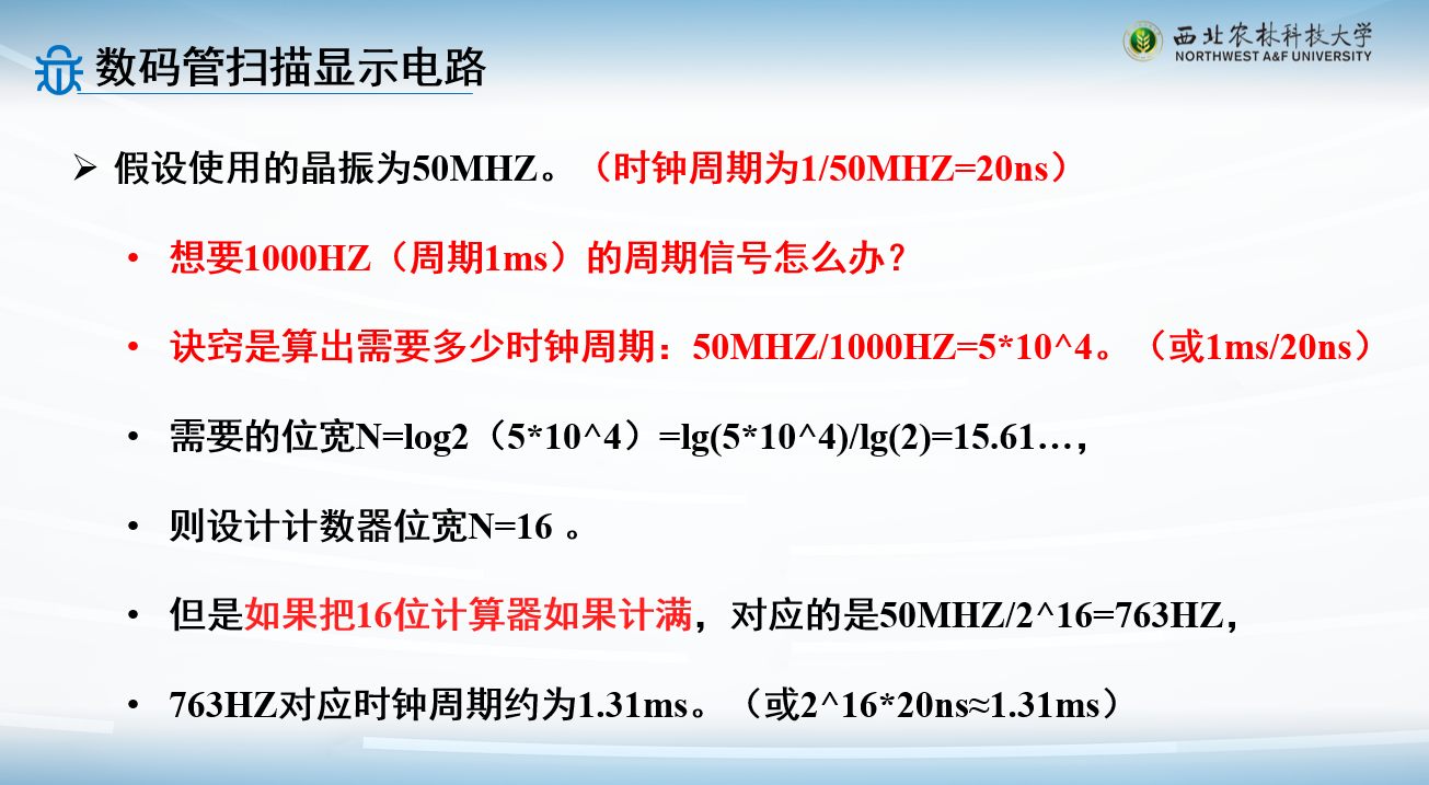
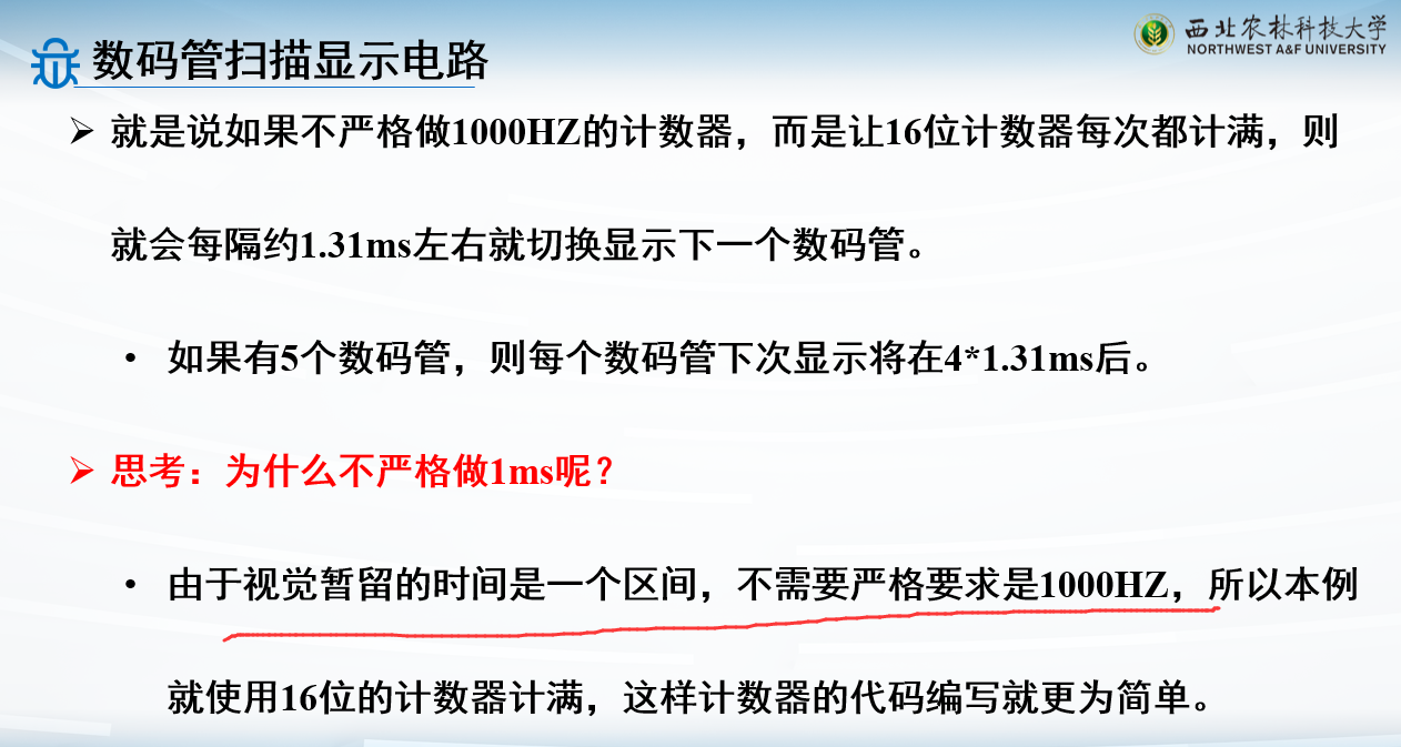
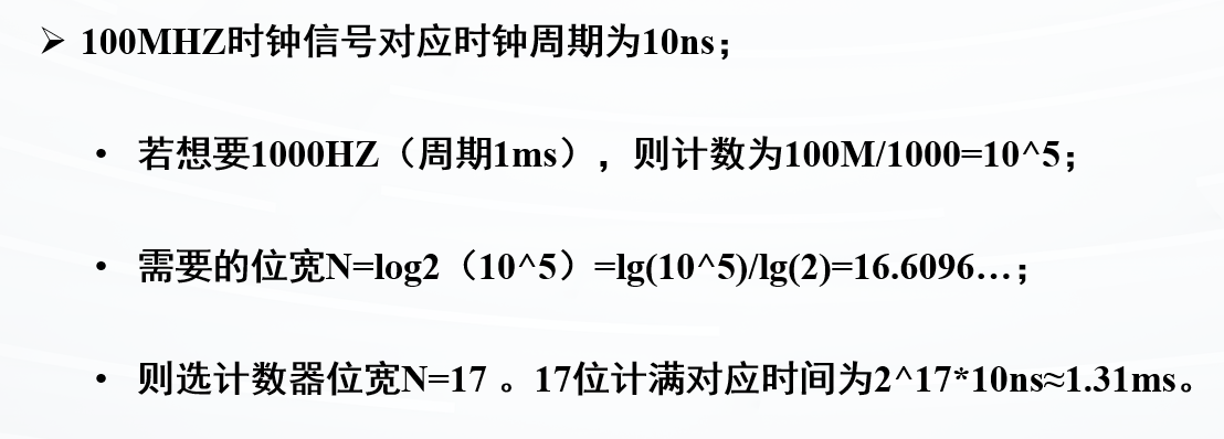
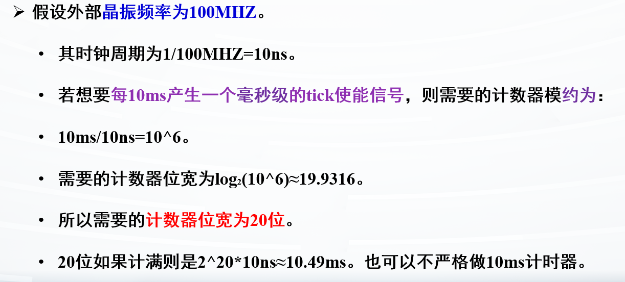
人眼的视觉暂留最佳频率是1000HZ左右,即时钟周期为1ms
输入为100MHZ,对应时钟周期为10ns
则计数值为\(\dfrac{10^{-3}s}{10\times10^{-9}s}=10^5\)
因为要考虑高位进位,所以需要算出对应的位宽
前面的计数器之所以可以不设位宽,因为前面的设计只需要考虑能不能存下计数的值,都可以用32位
但是这个设置位宽,是因为要考虑高位进位,作为控制信号
8个数码管,控制信号就是3位,即\(2^3=8\)
故最后需要17+3=20位的计数器
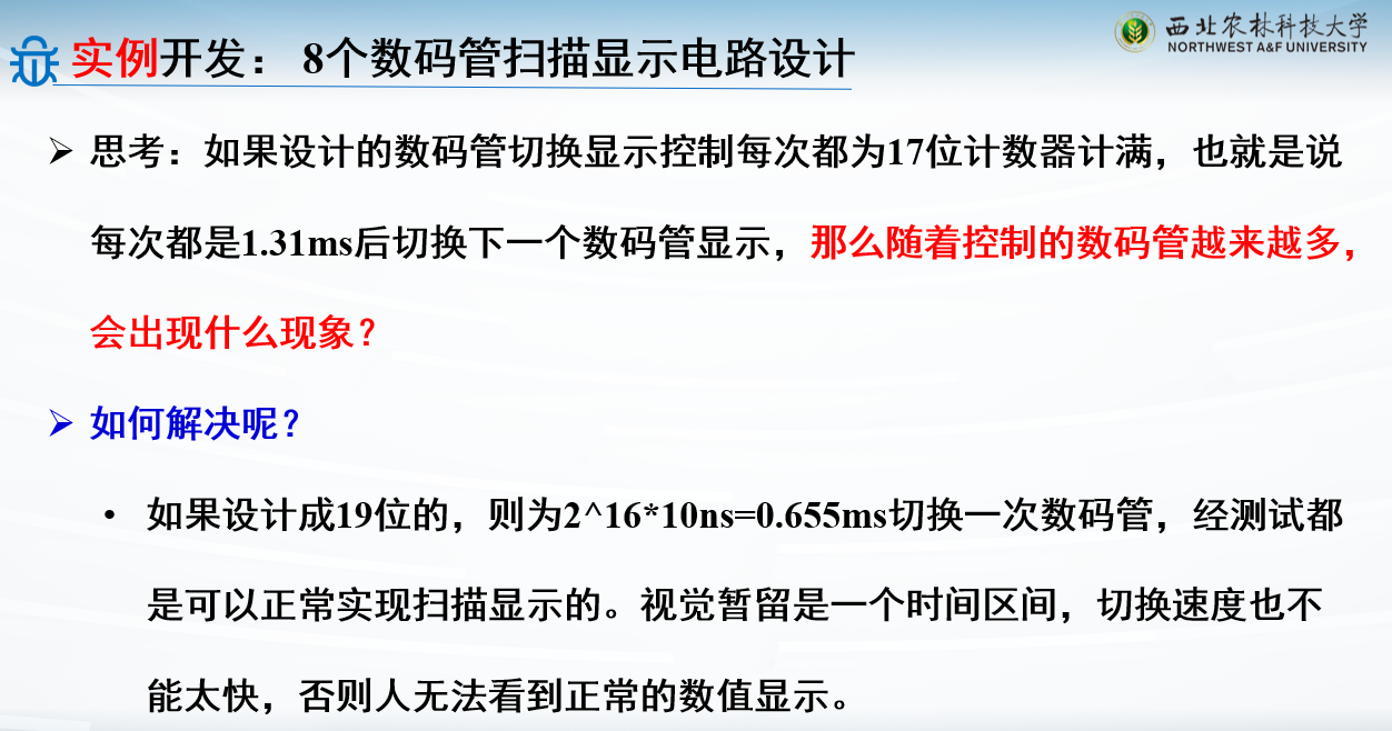
如果出现闪烁感,就要缩短计时时间了
结构设计:
8位的an信号用于选择让哪一个数码管亮:
1 2 3 4 5 6 7 8 9 10 11 12 13 14 15 16 17 18 19 20 21 22 23 24 25 26 27 28 29 30 31 32 33 34 35 36 37 38 39 40 41 42 43 44 45 46 47 48 49 50 51 52 53 54 55 56 57 58 59 60 61 62 63 64 65 66 67 68 69 70 71 72 73 74 75 76 77 78 79 80 81 82 83 84 85 86 `timescale 1ns / 1ps module scan_led_hex_disp ( input clk,rstn, input [3 :0 ] hex7,hex6,hex5,hex4,hex3,hex2,hex1,hex0, input [7 :0 ] dp_in, input [7 :0 ] sseg_select, output reg [7 :0 ] an, output reg dp, output reg [6 :0 ] sseg ); parameter N=19 ;reg [N-1 :0 ] regN;reg [3 :0 ] hex_in;always @(posedge clk or negedge rstn) if (!rstn) regN <= 0 ; else regN <= regN + 1 ; always @* case (regN[N-1 :N-3 ]) 3'b000 : begin an = 8'b1111_1110 | sseg_select; hex_in = hex0; dp = dp_in[0 ]; end 3'b001 : begin an = 8'b1111_1101 | sseg_select; hex_in = hex1; dp = dp_in[1 ]; end 3'b010 : begin an = 8'b1111_1011 | sseg_select; hex_in = hex2; dp = dp_in[2 ]; end 3'b011 : begin an = 8'b1111_0111 | sseg_select; hex_in = hex3; dp = dp_in[3 ]; end 3'b100 : begin an = 8'b1110_1111 | sseg_select; hex_in = hex4; dp = dp_in[4 ]; end 3'b101 : begin an = 8'b1101_1111 | sseg_select; hex_in = hex5; dp = dp_in[5 ]; end 3'b110 : begin an = 8'b1011_1111 | sseg_select; hex_in = hex6; dp = dp_in[6 ]; end default : begin an = 8'b0111_1111 | sseg_select; hex_in = hex7; dp = dp_in[7 ]; end endcase always @* begin case (hex_in) 4'd0 : sseg[6 :0 ] = 7'b1111110 ; 4'd1 : sseg[6 :0 ] = 7'b0110000 ; 4'd2 : sseg[6 :0 ] = 7'b1101101 ; 4'd3 : sseg[6 :0 ] = 7'b1111001 ; 4'd4 : sseg[6 :0 ] = 7'b0110011 ; 4'd5 : sseg[6 :0 ] = 7'b1011011 ; 4'd6 : sseg[6 :0 ] = 7'b1011111 ; 4'd7 : sseg[6 :0 ] = 7'b1110000 ; 4'd8 : sseg[6 :0 ] = 7'b1111111 ; 4'd9 : sseg[6 :0 ] = 7'b1111011 ; 4'd10 : sseg[6 :0 ] = 7'b1110111 ; 4'd11 : sseg[6 :0 ] = 7'b0011111 ; 4'd12 : sseg[6 :0 ] = 7'b1001110 ; 4'd13 : sseg[6 :0 ] = 7'b0111101 ; 4'd14 : sseg[6 :0 ] = 7'b1001111 ; default : sseg[6 :0 ]=7'b1000111 ; endcase end endmodule
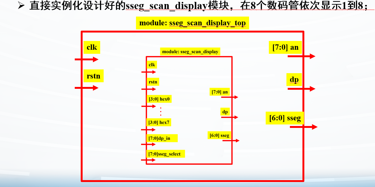
例子:在8个数码管依次显示1到8
1
2
3
4
5
6
7
8
9
10
11
12
13
14
15
16
17
18
19
20
21
22
23
24
25
26
27
28
29
module sseg_scan_display_top( input clk, input rstn, output [7 :0 ] an, output dp, output [6 :0 ]sseg ); scan_led_hex_disp u_scan_led_hex_disp( .clk (clk), .rstn (rstn), .hex7 (4'd1 ), .hex6 (4'd2 ), .hex5 (4'd3 ), .hex4 (4'd4 ), .hex3 (4'd5 ), .hex2 (4'd6 ), .hex1 (4'd7 ), .hex0 (4'd8 ), .dp_in (8'b0000_0000 ), .sseg_select (8'b0000_0000 ), .an (an), .dp (dp), .sseg (sseg) ); endmodule
如果模块写好了,就可以直接调用,很容易的
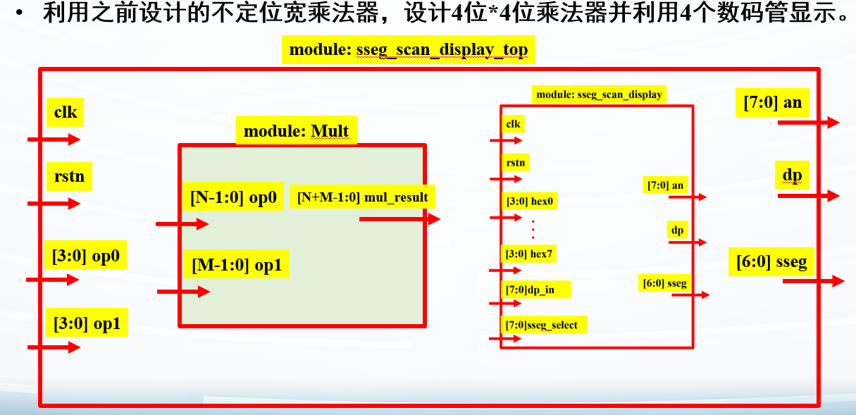
例子:设计乘法器并显示在数码管中
4位*4位,则结果为8位
之前写好的位移乘法:
1
2
3
4
5
6
7
8
9
10
11
12
13
14
15
module Mult (input [N-1 :0 ] op0,input [M-1 :0 ] op1,output reg [N+M-1 :0 ] mul_result ); parameter N=2 ;parameter M=2 ;integer i; always @* begin mul_result=0 ; for (i=0 ; i<M; i=i+1 ) if (op1[i]) mul_result=mul_result+(op0<<i); end endmodule
在数码管乘法中使用:
1
2
3
4
5
6
7
8
9
10
11
12
13
14
15
16
17
18
19
20
21
22
23
24
25
26
27
28
29
30
31
32
33
34
35
36
37
38
39
module sseg_scan_display_top( input clk, input rstn, input [3 :0 ] op0, input [3 :0 ] op1, output [7 :0 ] an, output dp, output [6 :0 ]sseg ); wire [7 :0 ] mul_temp;Mult #(.N(4),.M(4)) u_Mult ( .op0 (op0), .op1 (op1), .mul_result (mul_temp) ); scan_led_hex_disp u_scan_led_hex_disp( .clk (clk), .rstn (rstn), .hex7 (op0), .hex5 (op1), .hex3 (mul_temp[7 :4 ]), .hex2 (mul_temp[3 :0 ]), .dp_in (8'b0000_0000 ), .sseg_select (8'b0101_0011 ), .an (an), .dp (dp), .sseg (sseg) ); endmodule
结果:
但是这是16进制,不好看
1
2
3
4
5
6
7
8
9
10
11
12
13
14
15
16
17
18
19
20
21
22
23
24
25
26
27
28
29
30
31
32
33
34
35
36
37
38
39
module sseg_scan_display_top( input clk, input rstn, input [3 :0 ] op0, input [3 :0 ] op1, output [7 :0 ] an, output dp, output [6 :0 ]sseg ); wire [7 :0 ] mul_temp;Mult #(.N(4),.M(4)) u_Mult ( .op0 (op0), .op1 (op1), .mul_result (mul_temp) ); scan_led_hex_disp u_scan_led_hex_disp( .clk (clk), .rstn (rstn), .hex7 (op0/4'd10 ), .hex6 (op0%4'd10 ), .hex5 (op1/4'd10 ), .hex4 (op1%4'd10 ), .hex2 (mul_temp/8'd100 ), .hex1 (mul_temp/8'd10 -(mul_temp/8'd100 )*8'd10 ), .hex0 (mul_temp%10'd10 ), .dp_in (8'b0000_0000 ), .sseg_select (8'b0000_1000 ), .an (an), .dp (dp), .sseg (sseg) ); endmodule
在显示的时候,多用3个数码管,因为要显示10进制的数
其实很简单,在刚刚数码管显示电路里,我们已经实现了0-15的显示逻辑
现在只需要把数拆成十位和个位,就能直接带入显示
拆成十位:除10
拆成个位:余10
.hex7(op0/4'd10), .hex6(op0%4'd10),
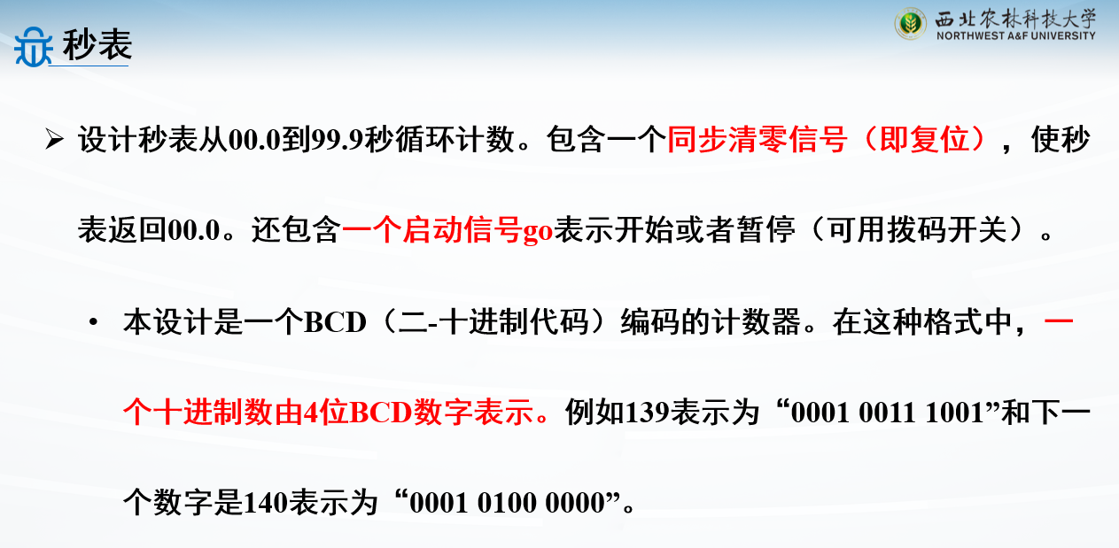
秒表设计
秒表实现方法有两种:
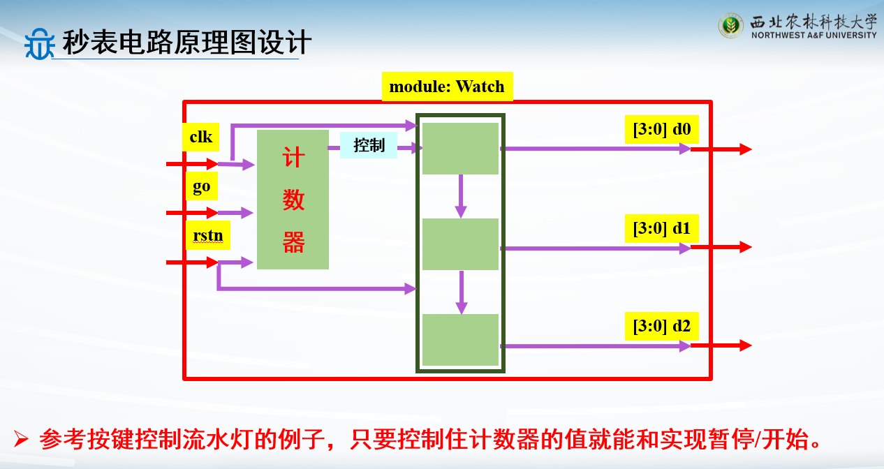
一种是跟呼吸灯一样,用最低位的计数器控制上面的位
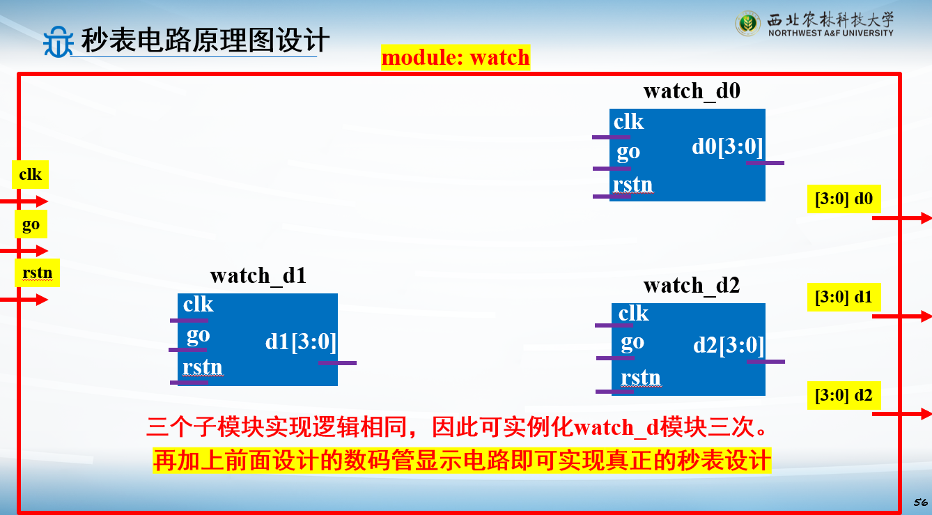
还有一种就是,每一位用单独的计数器控制
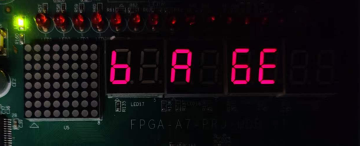
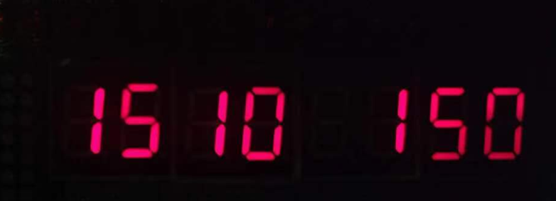
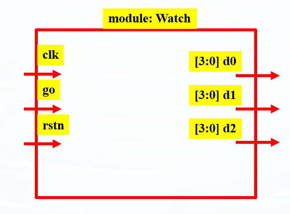
例子:秒表(进位)
1 2 3 4 5 6 7 8 9 10 11 12 13 14 15 16 17 18 19 20 21 22 23 24 25 26 27 28 29 30 31 32 33 34 35 36 37 38 39 40 41 42 43 44 45 46 47 48 49 50 51 52 53 54 55 56 57 58 59 `timescale 1ns / 1ps module Watch(input clk,input go,input rstn,output reg [3 :0 ] d0,output reg [3 :0 ] d1,output reg [3 :0 ] d2); parameter M=10000000 ;reg [23 :0 ] cnt;always @ (posedge clk) begin if (!rstn) cnt <= 0 ; else if (!go) cnt <= cnt; else if (cnt == M-1 ) cnt <= 0 ; else cnt <= cnt + 1 ; end always @ (posedge clk) begin if (!rstn) d0 <= 0 ; else if (d0 == 4'd9 & cnt == M-1 ) d0 <= 0 ; else if (cnt == M-1 ) d0 <= d0 + 1 ; else d0 <= d0; end always @ (posedge clk) begin if (!rstn) d1 <= 0 ; else if (d1 == 4'd9 & d0 == 4'd9 & cnt == M-1 ) d1 <= 0 ; else if (d0 == 4'd9 & cnt == M-1 ) d1 <= d1 + 1 ; else d1 <= d1; end always @ (posedge clk) begin if (!rstn) d2 <= 0 ; else if (d2 == 4'd9 & d1 == 4'd9 & d0 == 4'd9 & cnt == M-1 ) d2 <= 0 ; else if (d1 == 4'd9 & d0 == 4'd9 & cnt == M-1 ) d2 <= d2 + 1 ; else d2 <= d2; end endmodule
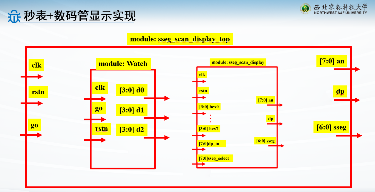
例子:秒表+数码管显示
调用秒表模块和数码管模块即可
1
2
3
4
5
6
7
8
9
10
11
12
13
14
15
16
17
18
19
20
21
22
23
24
25
26
27
28
29
30
31
32
33
34
35
36
37
38
39
40
41
42
43
44
module sseg_scan_display_top( input clk, input rstn, input go, output [7 :0 ] an, output dp, output [6 :0 ]sseg ); wire [3 :0 ] d0;wire [3 :0 ] d1;wire [3 :0 ] d2;Watch u_Watch( .clk (clk),.go (go),.rstn (rstn),.d0 (d0),.d1 (d1),.d2 (d2)); scan_led_hex_disp u_scan_led_hex_disp( .clk (clk), .rstn (rstn), .hex2 (d2), .hex1 (d1), .hex0 (d0), .dp_in (8'b0000_0010 ), .sseg_select (8'b1111_1000 ), .an (an), .dp (dp), .sseg (sseg) ); endmodule
例子:秒表(每位单独控制)
1 2 3 4 5 6 7 8 9 10 11 12 13 14 15 16 17 18 19 20 21 22 23 24 25 26 27 28 29 30 31 32 33 34 35 `timescale 1ns / 1ps module Watch(input clk,input go,input rstn,output reg [3 :0 ] d); parameter M=1_000_0000 ;reg [39 :0 ] cnt;always @ (posedge clk) begin if (!rstn) cnt <= 0 ; else if (!go) cnt <= cnt; else if (cnt == M-1 ) cnt <= 0 ; else cnt <= cnt + 1 ; end always @ (posedge clk) begin if (!rstn) d <= 0 ; else if (d == 4'd9 & cnt == M-1 ) d <= 0 ; else if (cnt == M-1 ) d <= d + 1 ; else d <= d; end endmodule
1
2
3
4
5
6
7
8
9
10
11
12
13
14
15
16
17
18
19
20
21
22
23
24
25
26
27
28
29
30
31
32
33
34
35
36
37
38
39
40
41
42
43
44
45
46
47
48
49
50
51
52
53
54
55
56
57
58
59
60
61
62
63
64
65
66
67
68
69
module sseg_scan_display_top( input clk, input rstn, input go, output [7 :0 ] an, output dp, output [6 :0 ]sseg ); wire [3 :0 ] d0;wire [3 :0 ] d1;wire [3 :0 ] d2;wire [3 :0 ] d3;wire [3 :0 ] d4;Watch u_Watch( .clk (clk),.go (go),.rstn (rstn),.d (d0)); Watch #(.M(1_0000_0000)) u1_Watch( .clk (clk),.go (go),.rstn (rstn),.d (d1)); Watch #(.M(10_0000_0000)) u2_Watch( .clk (clk),.go (go),.rstn (rstn),.d (d2)); Watch #(.M(40'd100_0000_0000)) u3_Watch( .clk (clk),.go (go),.rstn (rstn),.d (d3)); Watch #(.M(40'd1000_0000_0000)) u4_Watch( .clk (clk),.go (go),.rstn (rstn),.d (d4)); scan_led_hex_disp u_scan_led_hex_disp( .clk (clk), .rstn (rstn), .hex4 (d4), .hex3 (d3), .hex2 (d2), .hex1 (d1), .hex0 (d0), .dp_in (8'b0000_0010 ), .sseg_select (8'b1110_0000 ), .an (an), .dp (dp), .sseg (sseg) ); endmodule
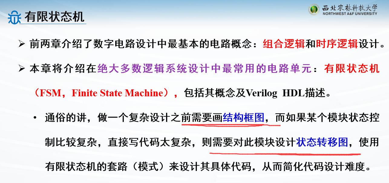
有限状态机设计
掌握Mealy和Moore型状态机的设计
掌握状态机代码实现
掌握按键消抖电路的状态机设计
有限状态机定义
时序逻辑分类
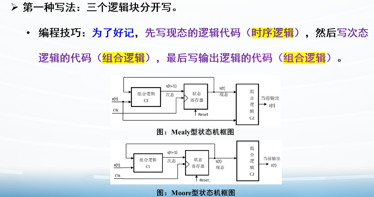
时序电路按电路输出对输入的依从关系分类:分Mealy型 和Moore型 电路模型
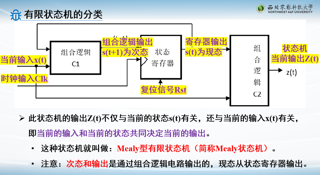
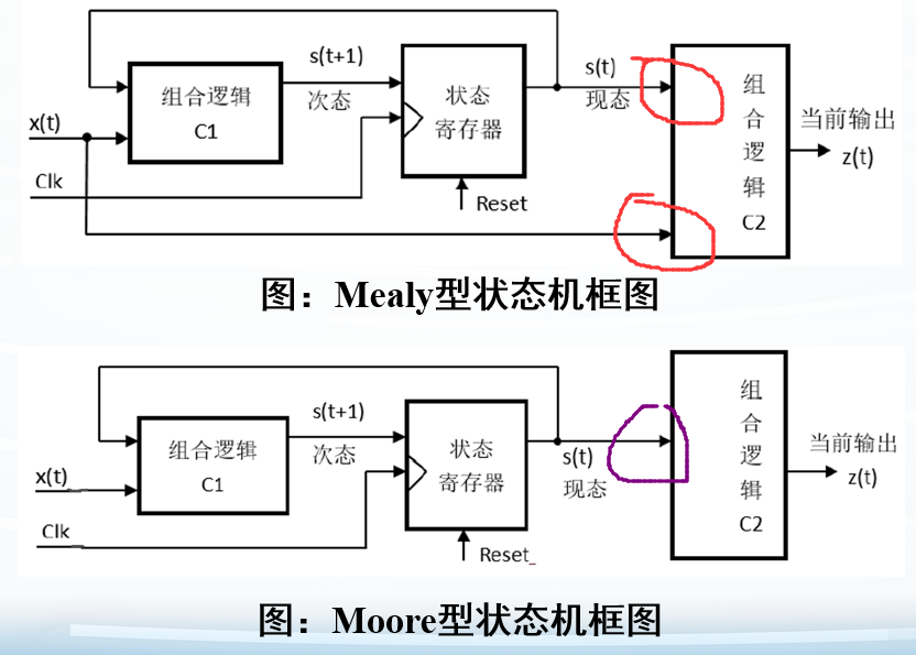
Mealy型电路:若时序逻辑电路的输出是电路输入和电路状态的函数 ,则称为Mealy型时序逻辑电路
Moore型电路:若时序逻辑电路的输出仅仅是电路状态的函数 ,则称为Moore型时序逻辑电路
Mealy型电路的输入和输出之间存在直接联系 ,而Moore型电路则是将全部输入转换成电路状态后再和输出建立联系
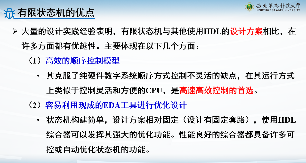
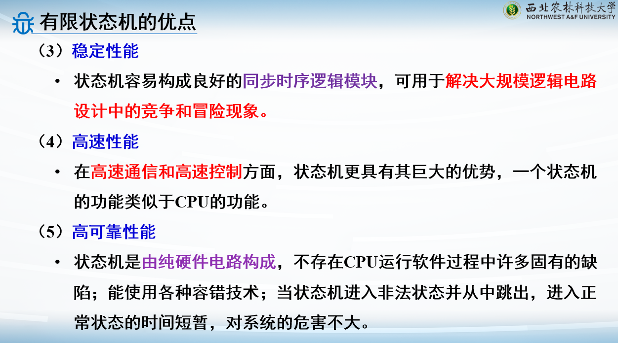
有限状态机优点
有限状态机分类
Mealy型
输出与当前状态和输入有关,就是Mealy型
Moore型
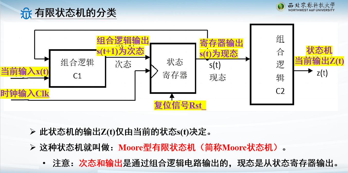
次态仅与现态有关,就是Moore型
区别和联系
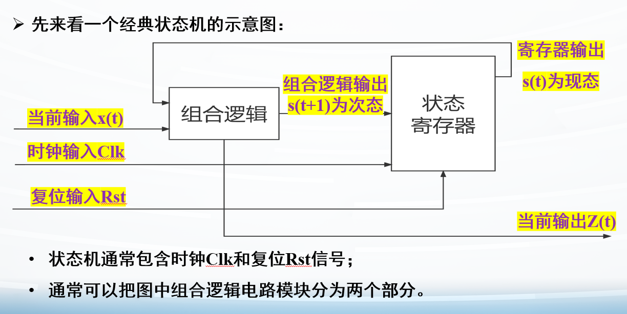
相同点: 1. 次态和输出两个模块都是用组合逻辑实现 2.
现态模块用时序 逻辑实现 3.
时钟Clk和复位信号Rst都是接到现态模块上 4. 次态都由输入和现态共同决定
不同点:
输出决定因素不一样
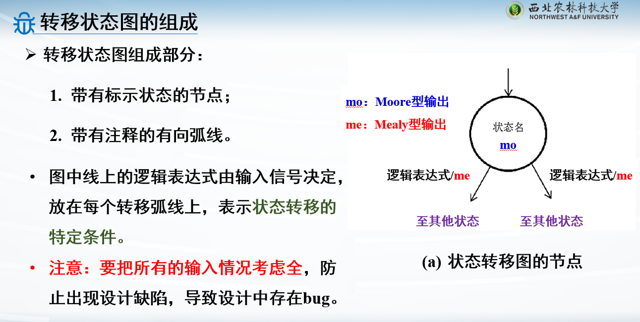
有限状态机表示方法
状态转移图,算法状态机图
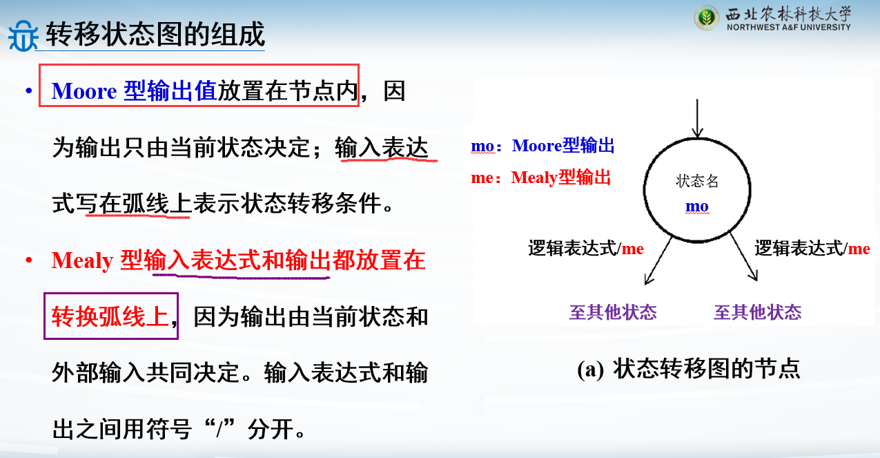
注意,两种状态机的状态转移图不一样
举例:
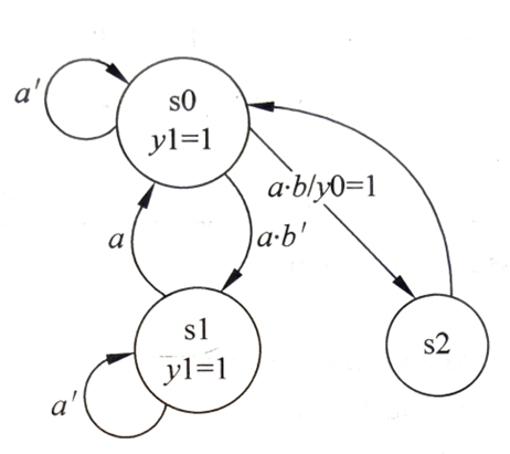
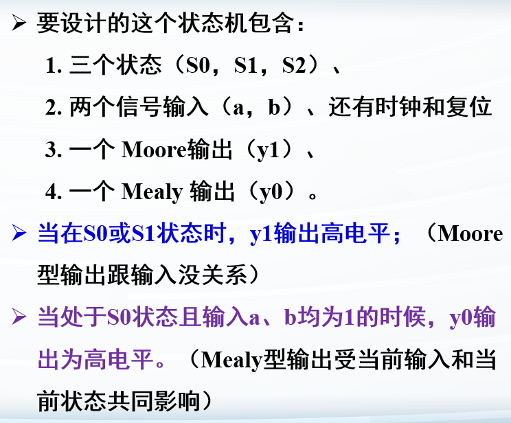
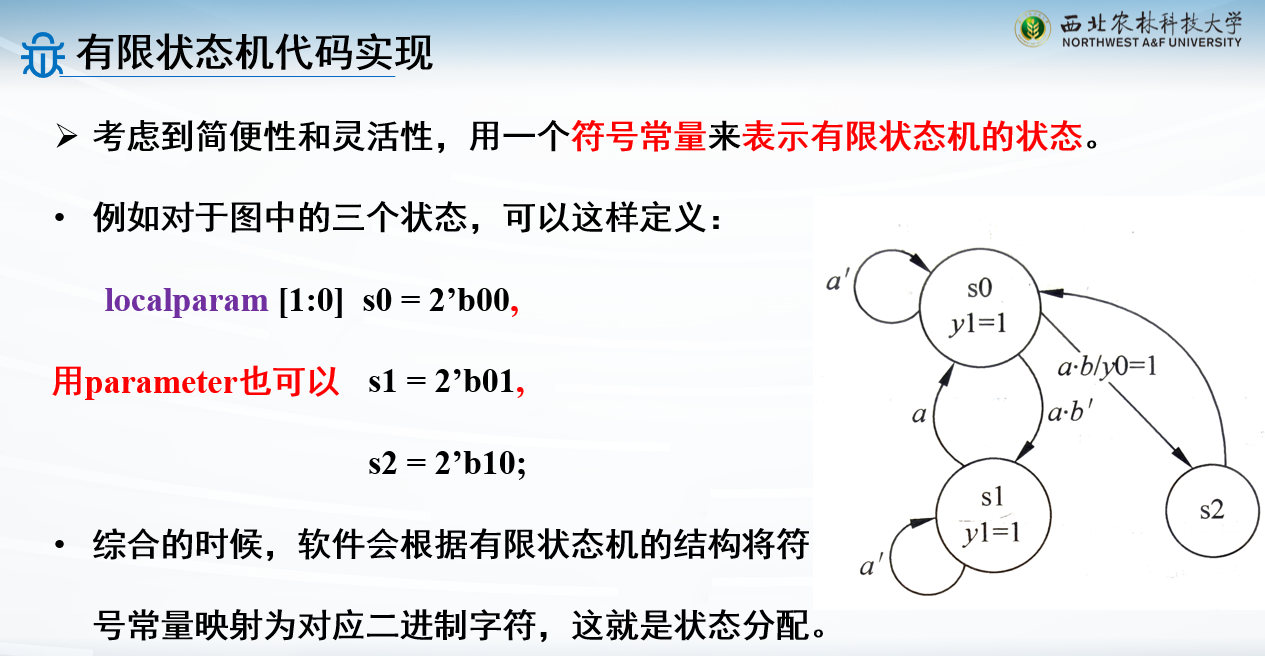
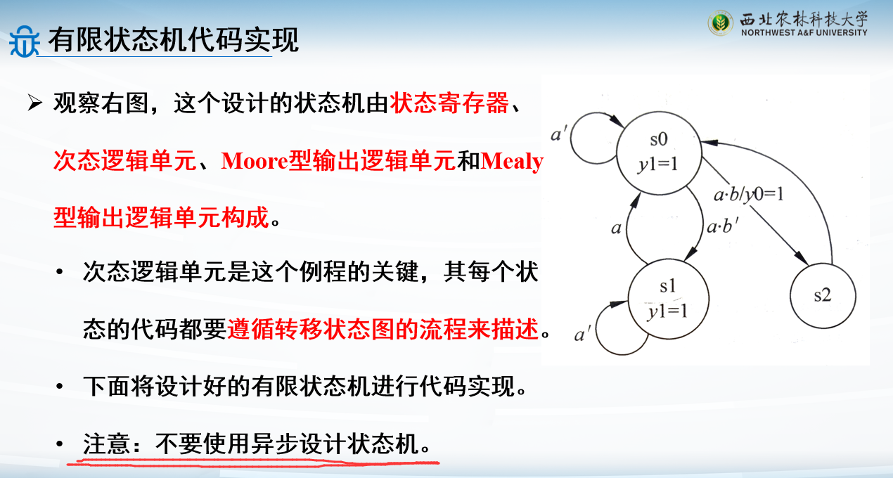
这个是两种状态机都有
s0,s1的输出y1写在状态里,转移弧线上只有输入,所以y1是Moore型输出
y0输出写在转移弧线上,说明输出与当前输入有关系,y0为Mealy型输出
转移弧线上a代表a=1,a'代表a=0
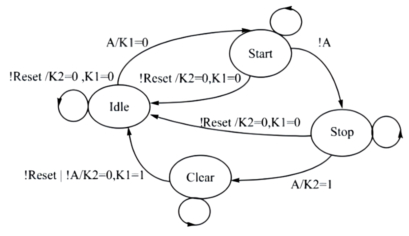
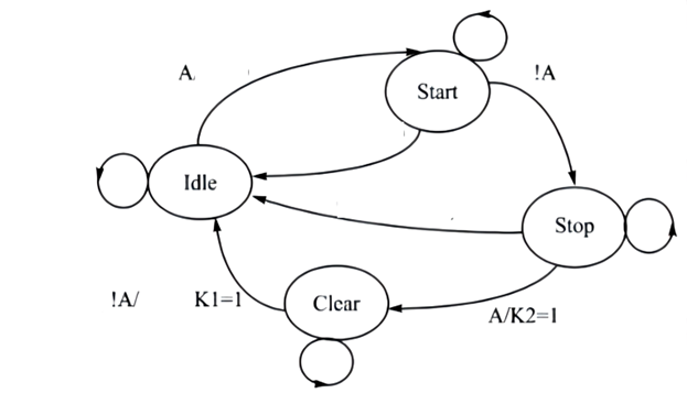
有问题的图:
4个状态
仅有A一个输入:因为Reset信号不能当做输入,这个图画的有问题
没有Moore型输出
K1,K2两个Mealy型输出
但是有不合理之处:Reset信号不能当做输入,因为Reset信号是接入现态逻辑 设计中,但是状态转移图描述的是次态逻辑和输入逻辑
有限状态机代码实现
如果用数电的知识:
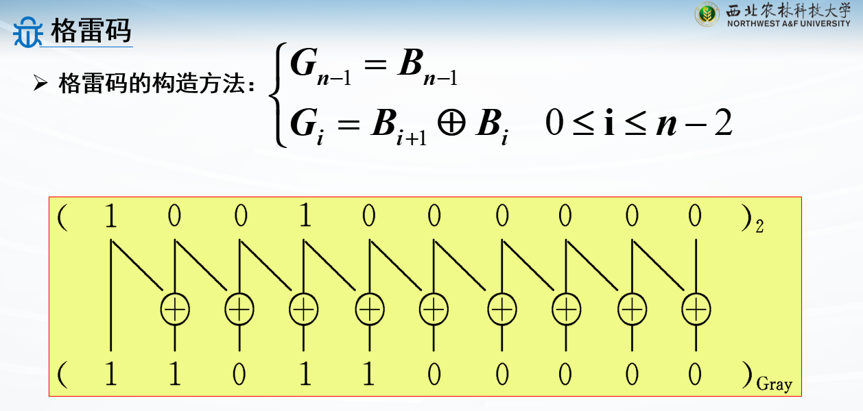
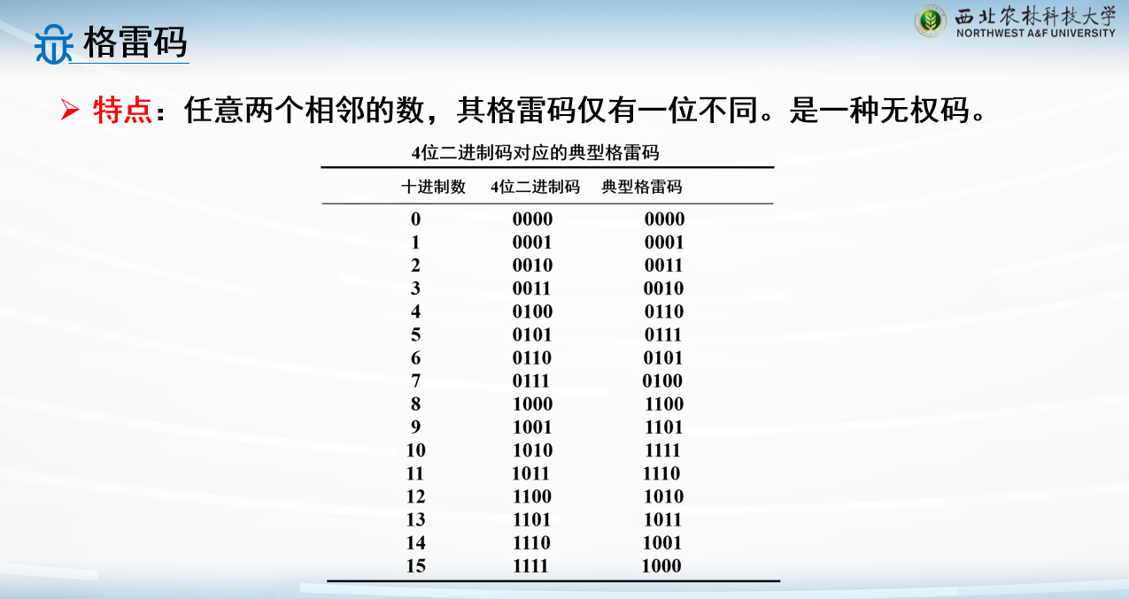
状态编码好像挺麻烦的?好像要用格雷码来着
但是这门课用FPGA,用独热码更多
设计的时候不要用异步设计
跟以前学到的一样,Reset放clk的always块里做判断就行
第一种写法:三个逻辑块分开写
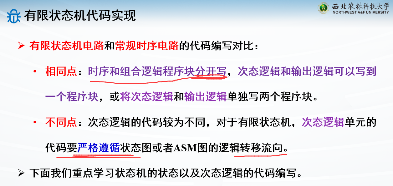
次态逻辑单元的代码要严格遵循状态图或者ASM图的逻辑转移流向
1
2
3
4
5
6
7
8
9
10
11
12
13
14
15
16
17
18
19
20
21
22
23
24
25
26
27
28
29
30
31
32
33
34
35
36
37
38
39
module Fsm_exp( input Clk,Rst_, input a,b, output y0,y1); localparam [1 :0 ] s0=2'b00 , s1=2'b01 , s2=2'b10 ; reg [1 :0 ] cs,nst; always @(posedge Clk) if (!Rst_) cs<=s0; else cs<=nst; always @* case (cs) s0: if (a) if (b) nst=s2; else nst=s1; else nst=s0; s1: if (a) nst=s0; else nst=s1; s2: nst=s0; default :nst=s0; endcase assign y1=(cs==s0)||(cs==s1); assign y0=(cs==s0)&&a&&b; endmodule
对应的testbench
1 2 3 4 5 6 7 8 9 10 11 12 13 14 15 16 17 18 19 20 21 22 23 24 25 26 27 `timescale 1ns / 1ps module Fsm_exp_testbench; reg Clk,Rst_; reg a,b; wire y0,y1; initial begin a=1 ; b=1 ; Clk=0 ; Rst_=1 ; #5 Rst_=0 ; #3 Rst_=1 ; end always #10 a=~a; always #20 b=~b; always #7 Clk=~Clk; initial #100 $finish ; Fsm_exp U_Fsm_exp(Clk,Rst_,a,b,y0,y1); endmodule
有限状态机最重要的逻辑,就是次态切换逻辑
剩下的现态只需要最基本的时序,输出只需要看图
第二种写法:次态和输出模块结合在一起
输出定义为reg,注意赋初值
1
2
3
4
5
6
7
8
9
10
11
12
13
14
15
16
17
18
19
20
21
22
23
24
25
26
27
28
29
30
31
32
33
34
35
36
37
38
39
module Fsm_exp( input Clk,Rst_, input a,b, output reg y0,y1); localparam [1 :0 ] s0=2'b00 , s1=2'b01 , s2=2'b10 ; reg [1 :0 ] cs,nst; always @(posedge Clk ) if (!Rst_) cs<=s0; else cs<=nst; always @* begin nst=cs; y0=1'b0 ; y1=1'b0 ; case (cs) s0: begin y1=1'b1 ; if (a) if (b) begin nst=s2; y0=1'b1 ; end else nst=s1; end s1: begin y1=1'b1 ; if (a) nst=s0; end s2: nst=s0; default :nst=s0; endcase end endmodule
状态机设计实例
状态机实现模型
1
2
3
4
5
6
7
8
9
10
11
12
13
14
15
16
17
18
19
20
21
22
23
24
25
26
27
28
29
30
31
32
33
34
35
36
37
38
39
40
41
42
43
44
45
46
47
48
49
50
51
52
53
54
55
56
57
58
module fsm(Clock, Reset, A, K2, K1); input Clock, Reset, A; output K2, K1; reg K2, K1; reg [1 :0 ] state, nextstate; parameter Idle = 2'b00 , Start = 2'b01 , Stop = 2'b10 , Clear = 2'b11 ; always @(posedge Clock) if (!Reset) state <= Idle; else state <= nextstate; always @* case (state) Idle: if (A) nextstate = Start; else nextstate = Idle; Start: if (!A) nextstate = Stop; else nextstate = Start; Stop: if (A) nextstate = Clear; else nextstate = Stop; Clear: if (!A) nextstate = Idle; else nextstate = Clear; default : nextstate = 2'bxx ; endcase always @* if (state == Clear && !A) K1 = 1 ; else K1 = 0 ; always @* if (state == Stop && A) K2 = 1 ; else K2 = 0 ; endmodule
序列检测器
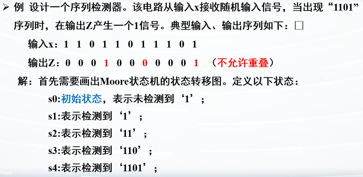
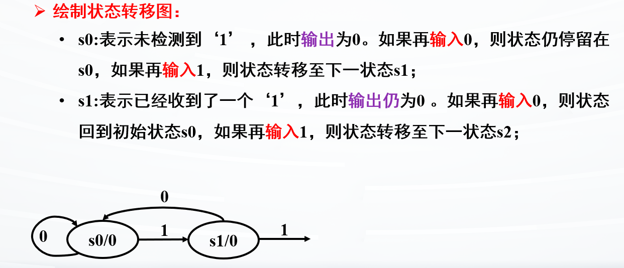
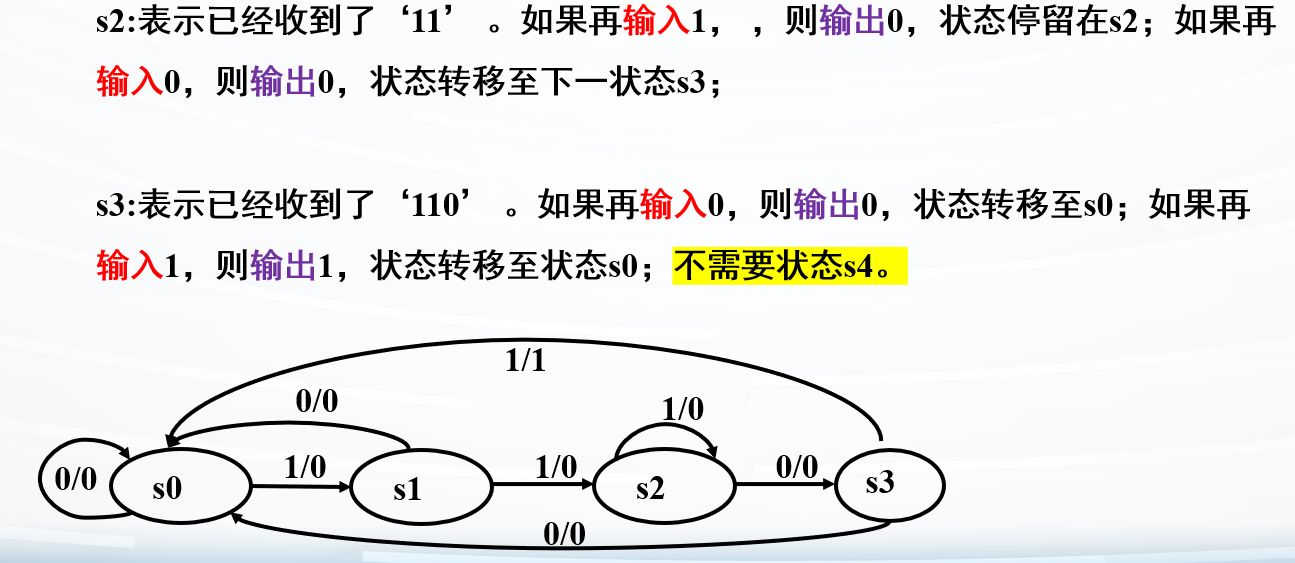
例子:基于Moore状态机设计序列检测器
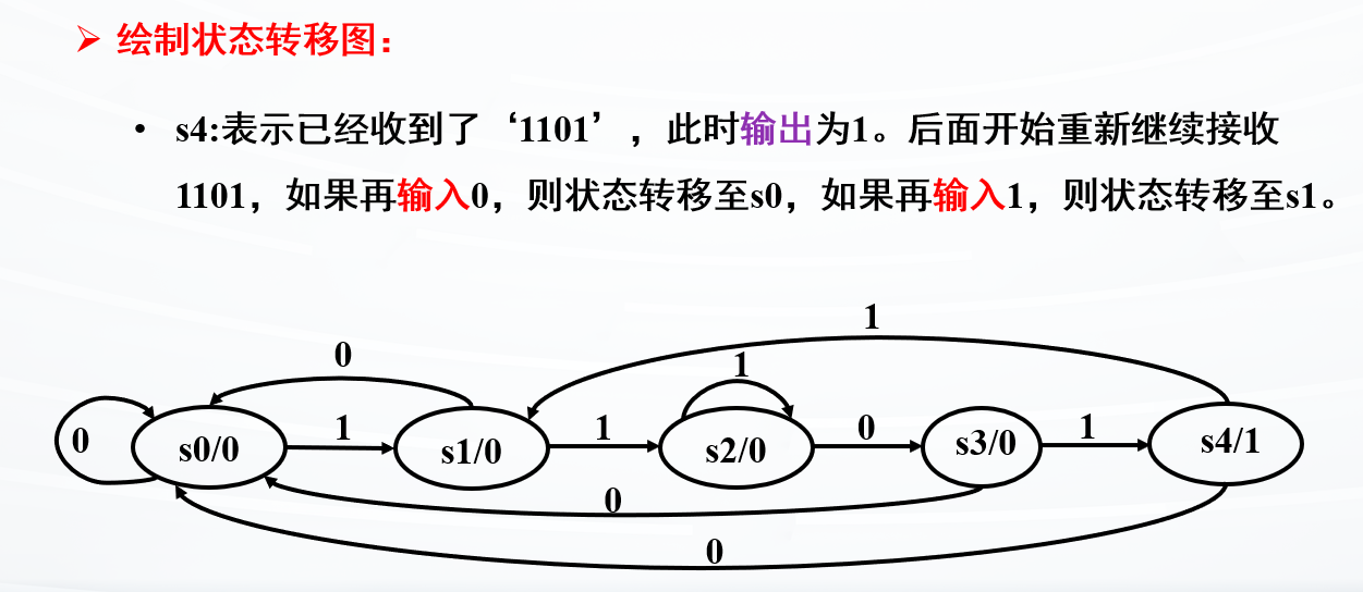
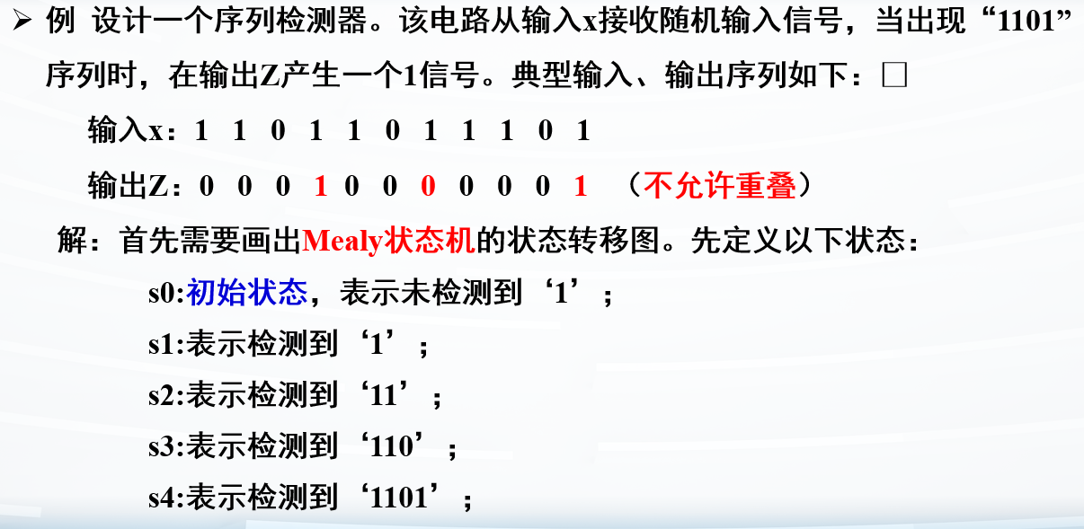
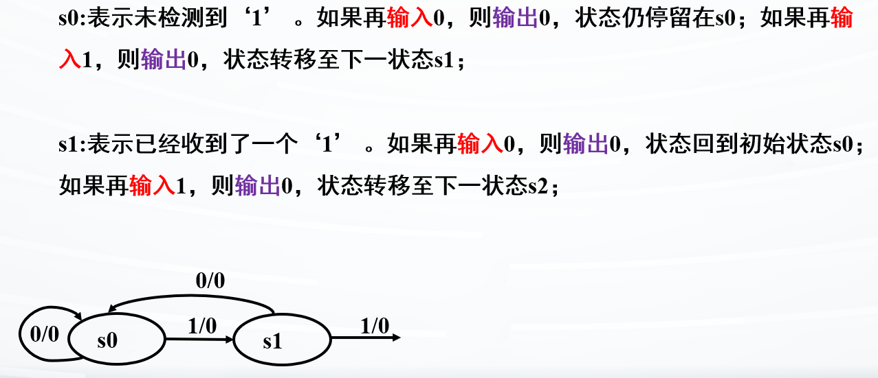
不允许重叠,则输出后直接回到初态
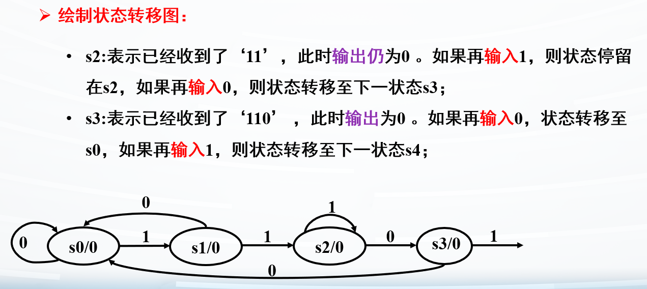
设计状态还是挺好设计的,针对序列设计就行
比如序列检测为1101
就设计初态、检测第一个1,检测11,检测110,检测1101,共5个状态
注意11状态时,再检测到1,状态停留
1
2
3
4
5
6
7
8
9
10
11
12
13
14
15
16
17
18
19
20
21
22
23
24
25
26
27
28
29
30
31
32
33
34
35
36
37
38
module Seq_det_moore( input clk,rstn, input din, output y); localparam [2 :0 ] s0=3'b000 , s1=3'b001 , s2=3'b010 , s3=3'b011 , s4=3'b100 ; reg [2 :0 ] cs,nst; always @(posedge clk ) if (!rstn) cs <= s0; else cs <= nst; always @* begin case (cs) s0: if (din) nst = s1; else nst = s0; s1: if (din) nst = s2; else nst = s0; s2: if (din) nst = s2; else nst = s3; s3: if (din) nst = s4; else nst = s0; s4: if (din) nst = s1; else nst = s0; default : nst = s0; endcase end assign y = (cs == s4); endmodule
例子:基于Mealy状态机设计序列检测器
注意:Mealy与Moore的不同,这里会少一个状态
1
2
3
4
5
6
7
8
9
10
11
12
13
14
15
16
17
18
19
20
21
22
23
24
25
26
27
28
29
30
31
module Seq_det_mealy(clk,rstn,din, y);input clk,rstn,din; output reg y; localparam [1 :0 ] s0 = 2'b00 , s1 = 2'b01 , s2 = 2'b10 , s3 = 2'b11 ; reg [2 :0 ] cs,nst; always @(posedge clk ) if (!rstn) cs <= s0; else cs <= nst; always @* begin case (cs) s0: if (din) nst=s1; else nst=s0; s1: if (din) nst=s2; else nst=s0; s2: if (din) nst=s2; else nst=s3; s3: nst=s0; default : nst=s0; endcase end always @* begin if ((cs == s3)&&(din == 1 )) y = 1 ; else y = 0 ; end endmodule
按键消抖电路设计
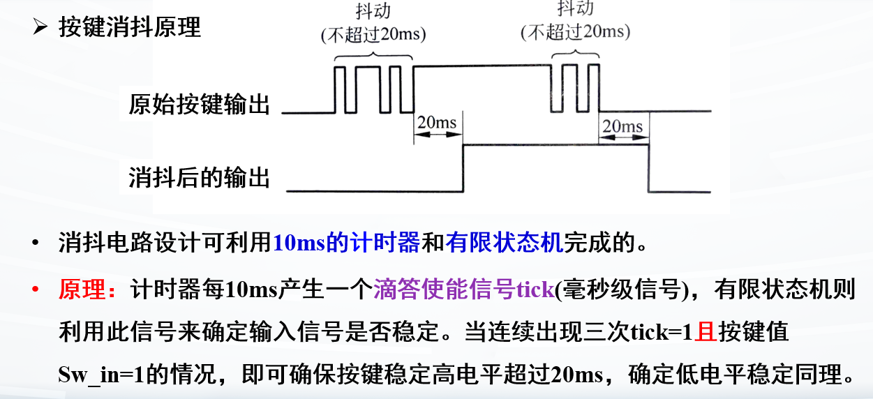
用硬件实现按键消抖,会占空间,开发板没有这么大空间
所以就用软件实现按键消抖
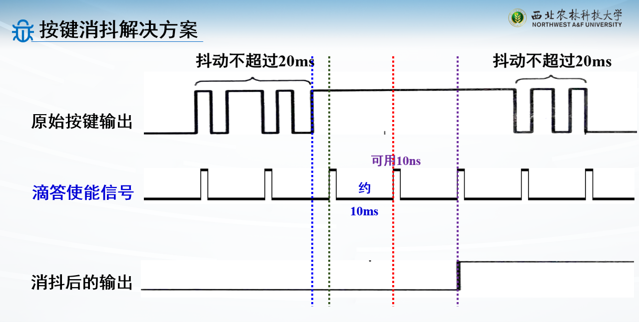
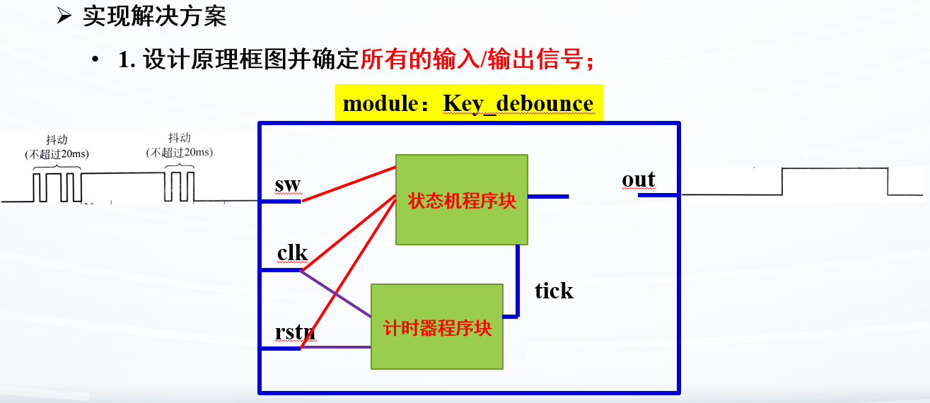
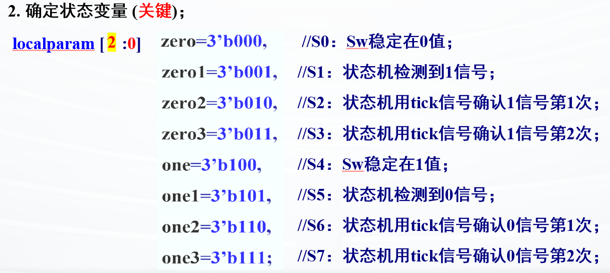
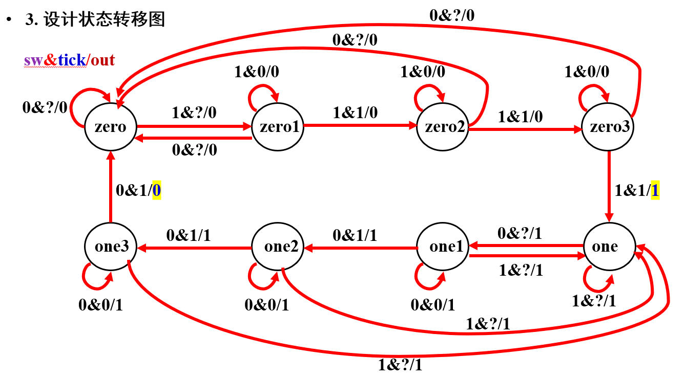
引入滴答使能信号tick,10ms一个
按键最多抖动20ms,所以如果连续3次出现稳定的tick=1,就可以确定此时按键稳定
例子:有限状态机设计按键消抖
挺麻烦
1
2
3
4
5
6
7
8
9
10
11
12
13
14
15
16
17
18
19
20
21
22
23
24
25
26
27
28
29
30
31
32
33
34
35
36
37
38
39
40
41
42
43
44
45
46
47
48
49
50
51
52
53
54
55
56
57
58
59
60
61
62
63
64
65
66
67
68
69
70
71
72
73
74
75
76
77
78
79
80
81
module Key_debounce(sw,clk,rstn,out);input sw,clk,rstn;output reg out;parameter N = 20 ;localparam [2 :0 ] zero = 3'b000 , zero1 = 3'b001 , zero2 = 3'b010 , zero3 = 3'b011 , one = 3'b100 , one1 = 3'b101 , one2 = 3'b110 , one3 = 3'b111 ; reg [2 :0 ] cs,nst;wire tick;reg [N-1 :0 ] cnt;always @(posedge clk ) begin if (!rstn) cnt <= 0 ; else cnt <= cnt + 1 ; end assign tick = (cnt == 0 ) ? 1 : 0 ;always @(posedge clk ) begin if (!rstn) cs <= zero; else cs <= nst; end always @* begin nst=cs; case (cs) zero: if (sw) nst = zero1; zero1: if (!sw) nst = zero; else if (tick) nst = zero2; zero2: if (!sw) nst = zero; else if (tick) nst = zero3; zero3: if (!sw) nst = zero; else if (tick) nst = one; one: if (!sw) nst = one1; one1: if (sw) nst = one; else if (tick) nst = one2; one2: if (sw) nst = one; else if (tick) nst = one3; one3: if (sw) nst = one; else if (tick) nst = zero; endcase end always @* begin out = 1'b0 ; case (cs) one,one1,one2: out = 1'b1 ; one3: if ({sw,tick}!=2'b01 ) out = 1'b1 ; zero3: if (sw & tick) out = 1'b1 ; endcase end endmodule
对应的testbench
1 2 3 4 5 6 7 8 9 10 11 12 13 14 15 16 17 18 19 20 21 22 23 24 25 26 27 28 29 30 `timescale 1ns / 1ps module tb_Key_debounce;reg clk,sw,rstn;wire out;Key_debounce #(.N(2)) u_Key_debounce (.sw (sw),.clk (clk),.rstn (rstn),.out (out)); always #2 clk=~clk;initial begin sw=0 ;clk=0 ; rstn=1 ; #5 sw=1 ; #1 sw=0 ; #1 sw=1 ; #1 sw=0 ; #2 sw=1 ; #100 sw=0 ; #1 sw=1 ; #1 sw=0 ; #2 sw=1 ; #1 sw=0 ; end initial begin #2 rstn=0 ; #2 rstn=1 ; end initial #300 $finish ;endmodule
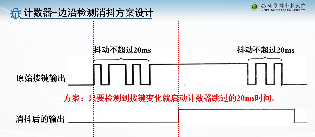
例子:计数器+按键边沿检测实现按键消抖
检测到按键,直接跳20ms就行
最好用这种写法
1
2
3
4
5
6
7
8
9
10
11
12
13
14
15
16
17
18
19
20
21
22
23
24
25
26
27
28
29
30
31
32
module Key_debounce(sw,clk,rstn,out);input sw,clk,rstn;output reg out;parameter N = 25 ; parameter M = 200_0000 ;reg [N-1 :0 ] cnt;wire sw_edge;edge_test u_edge_test( .sys_clk (clk ), .sys_rst_n (rstn ), .a (sw), .a_edge (sw_edge ) ); always @(posedge clk) begin if (!rstn) cnt <= 0 ; else if (sw_edge) cnt <= 0 ; else cnt <= cnt+1 ; end always @(posedge clk) begin if (!rstn) out <= 1 ; else if (cnt == M-1 ) out <= sw; else out <= out; end endmodule
UART串口通信
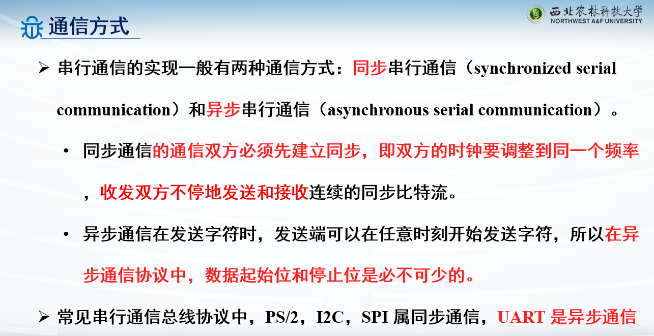
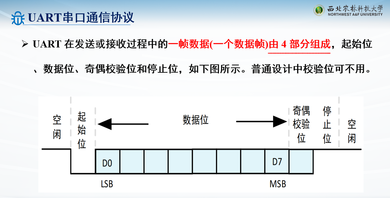
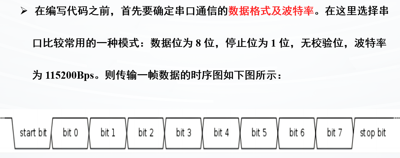
本章学的是异步通信,所以会有数据格式
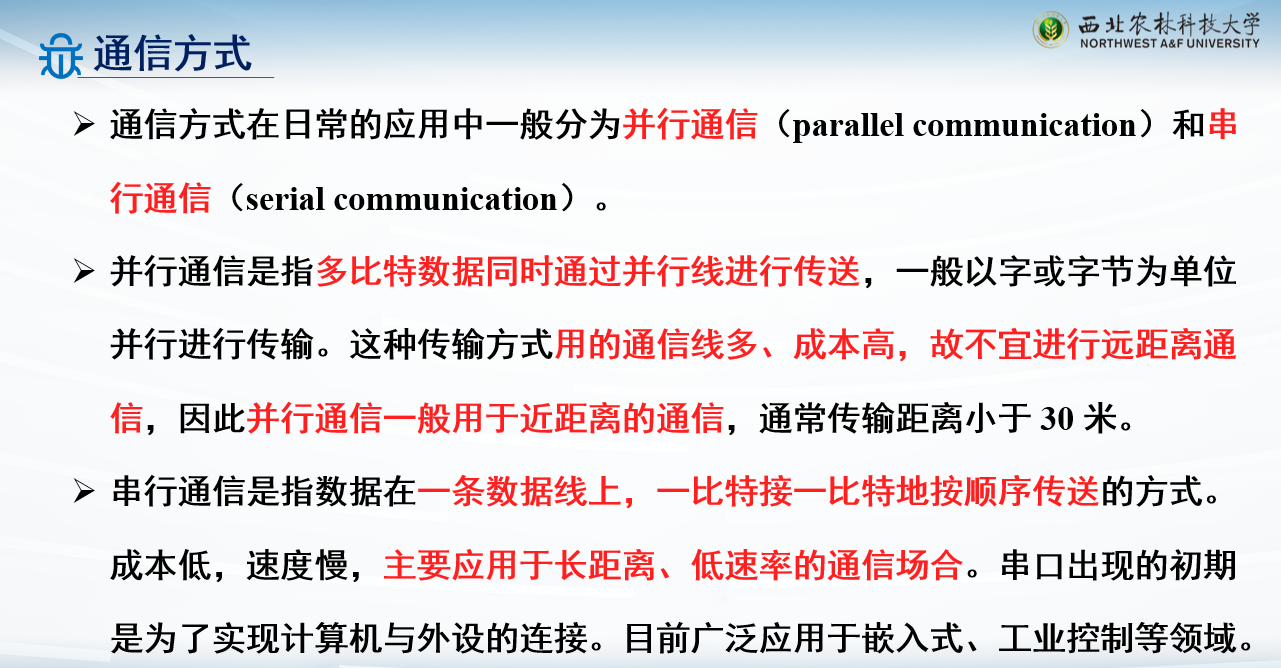
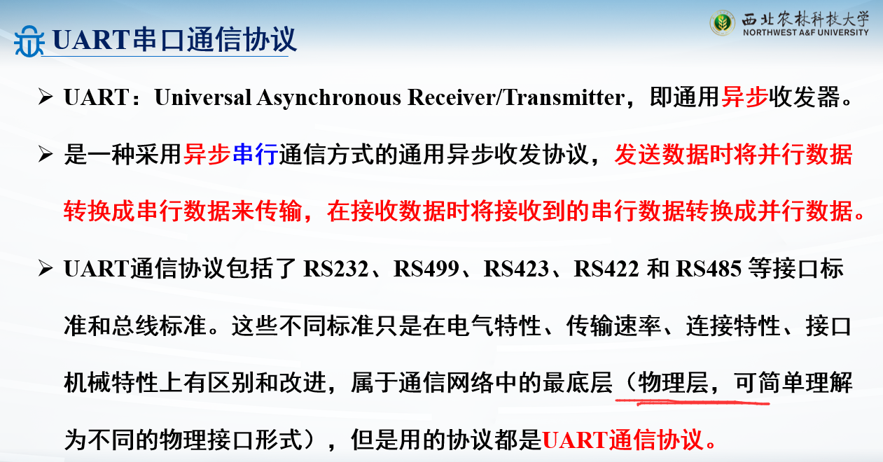
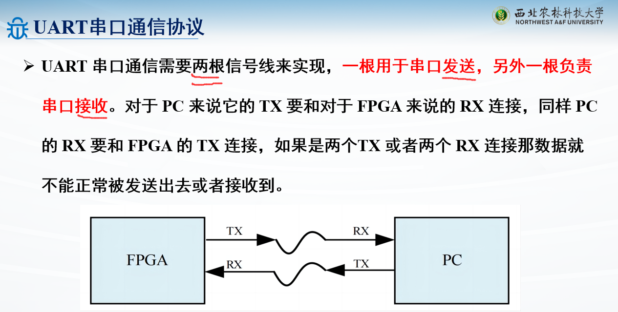
UART串口通信协议
UART:Universal Asynchronous
Receiver/Transmitter,即通用异步收发器
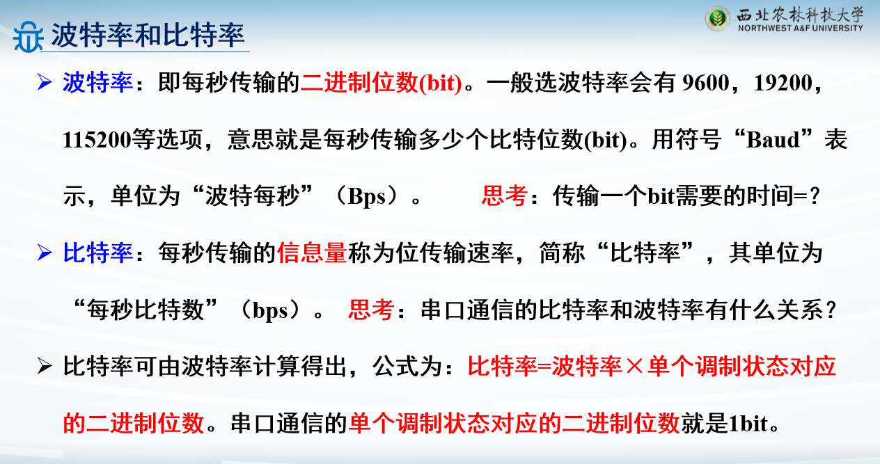
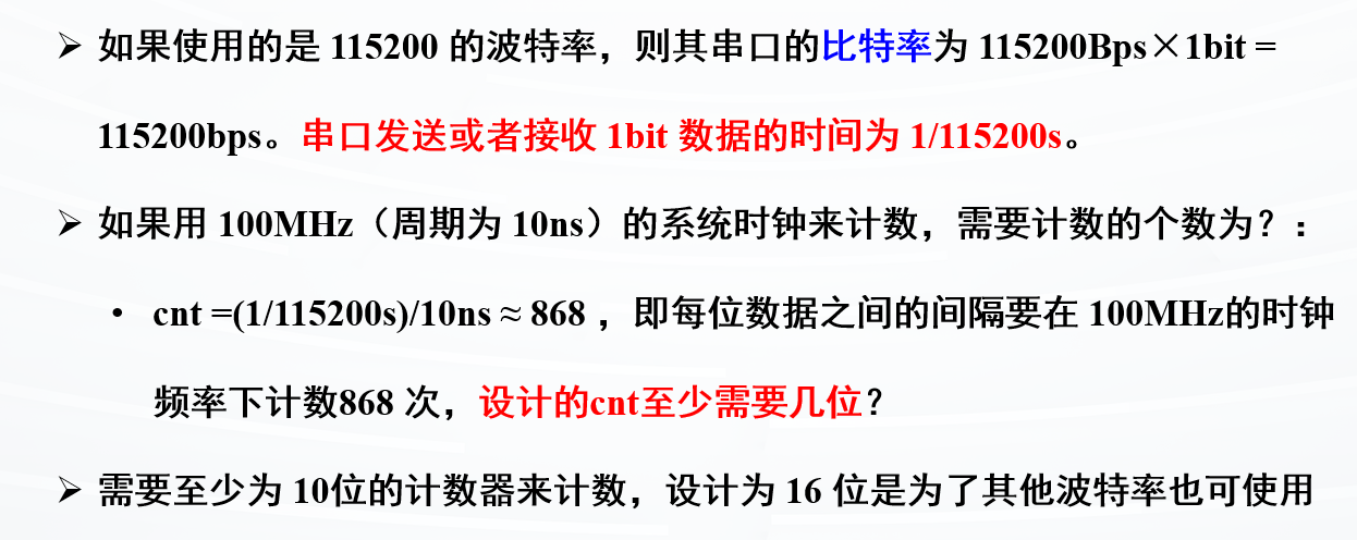
波特率比特率
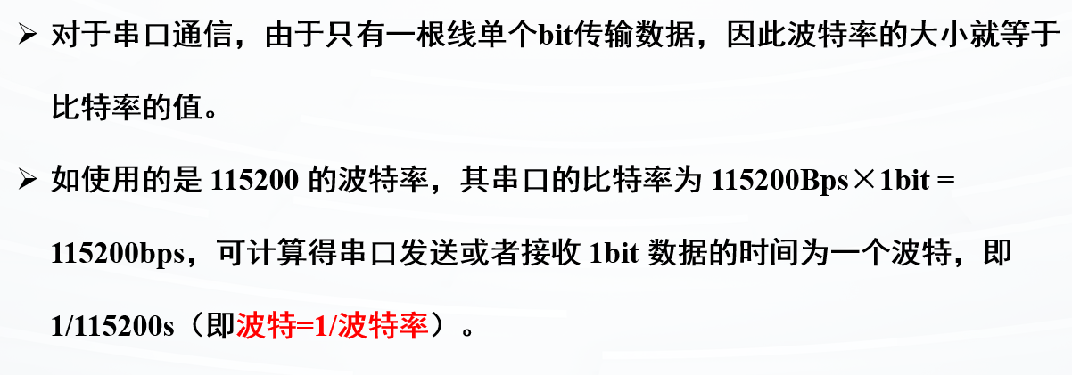
对串口通信,波特率等于比特率,因为串口通信传输的信息就是1位二进制
逻辑框图分析设计
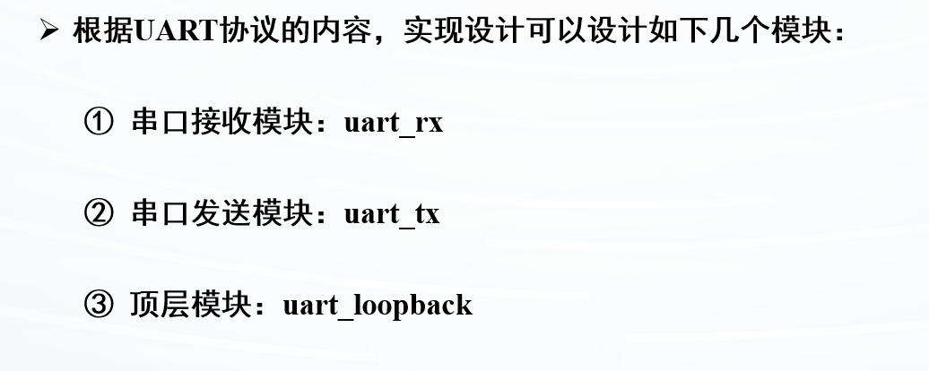
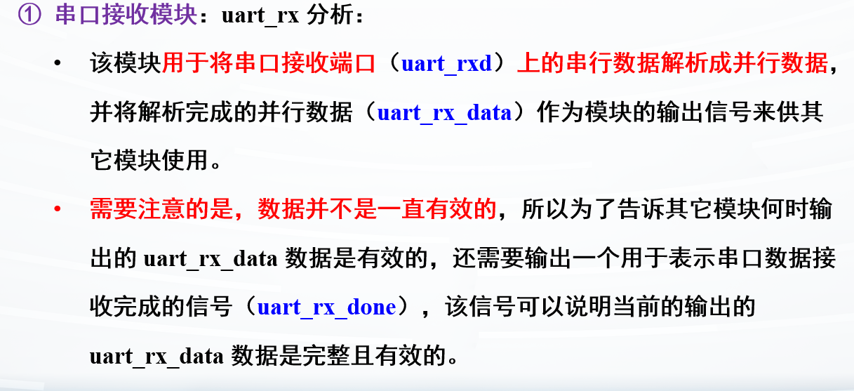
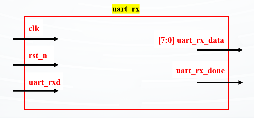
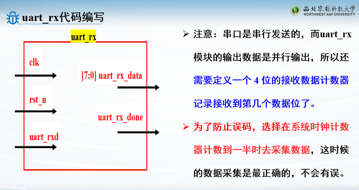
串口接收模块
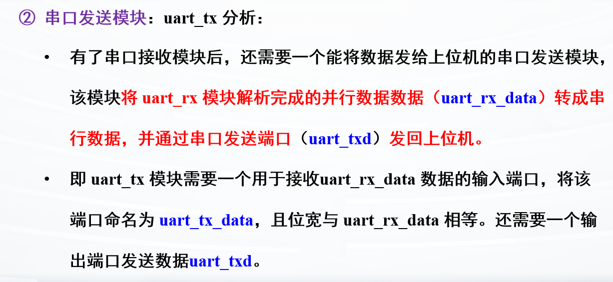
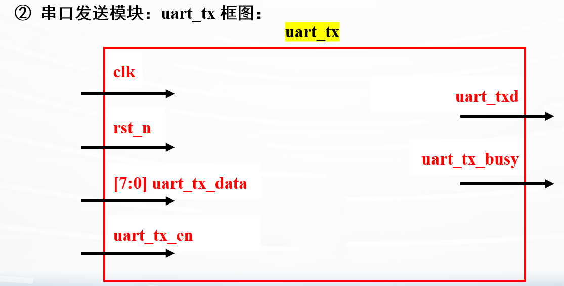
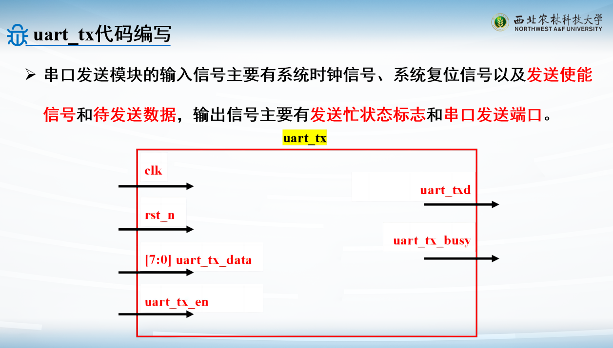
串口发送模块
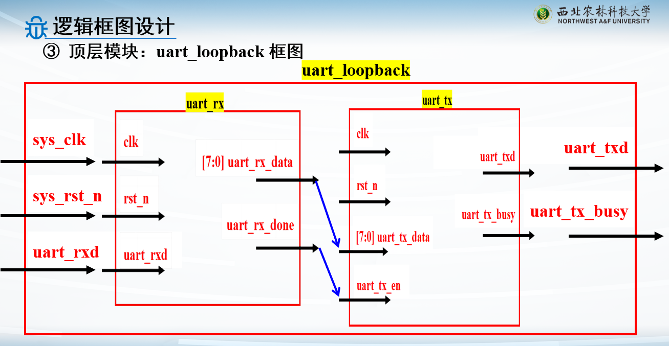
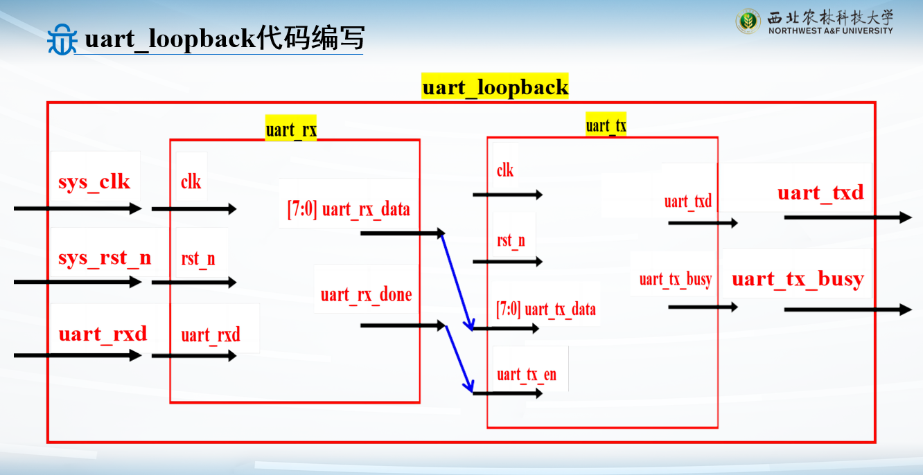
顶层模块
各模块代码实现
接收模块
图一乐就好
1
2
3
4
5
6
7
8
9
10
11
12
13
14
15
16
17
18
19
20
21
22
23
24
25
26
27
28
29
30
31
32
33
34
35
36
37
38
39
40
41
42
43
44
45
46
47
48
49
50
51
52
53
54
55
56
57
58
59
60
61
62
63
64
65
66
67
68
69
70
71
72
73
74
75
76
77
78
79
80
81
82
83
84
85
86
87
88
89
90
91
92
93
94
95
96
97
98
99
100
101
102
103
104
105
106
107
108
109
110
111
112
113
114
115
116
117
118
119
120
121
122
123
124
125
126
127
128
129
module uart_rx( input clk , input rst_n , input uart_rxd , output reg uart_rx_done, output reg [7 :0 ] uart_rx_data ); parameter CLK_FREQ = 1_0000_0000 ; parameter UART_BPS = 115200 ; localparam BAUD_CNT_MAX = CLK_FREQ/UART_BPS; reg uart_rxd_d0;reg uart_rxd_d1;reg uart_rxd_d2;reg rx_flag ; reg [3 :0 ] rx_cnt ; reg [15 :0 ] baud_cnt ; reg [7 :0 ] rx_data_t ; wire start_en;assign start_en = uart_rxd_d2 & (~uart_rxd_d1) & (~rx_flag);always @(posedge clk or negedge rst_n) begin if (!rst_n) begin uart_rxd_d0 <= 1'b0 ; uart_rxd_d1 <= 1'b0 ; uart_rxd_d2 <= 1'b0 ; end else begin uart_rxd_d0 <= uart_rxd; uart_rxd_d1 <= uart_rxd_d0; uart_rxd_d2 <= uart_rxd_d1; end end always @(posedge clk or negedge rst_n) begin if (!rst_n) rx_flag <= 1'b0 ; else if (start_en) rx_flag <= 1'b1 ; else if ((rx_cnt == 4'd9 ) && (baud_cnt == BAUD_CNT_MAX/2 - 1'b1 )) rx_flag <= 1'b0 ; else rx_flag <= rx_flag; end always @(posedge clk or negedge rst_n) begin if (!rst_n) baud_cnt <= 16'd0 ; else if (rx_flag) begin if (baud_cnt < BAUD_CNT_MAX - 1'b1 ) baud_cnt <= baud_cnt + 16'b1 ; else baud_cnt <= 16'd0 ; end else baud_cnt <= 16'd0 ; end always @(posedge clk or negedge rst_n) begin if (!rst_n) rx_cnt <= 4'd0 ; else if (rx_flag) begin if (baud_cnt == BAUD_CNT_MAX - 1'b1 ) rx_cnt <= rx_cnt + 1'b1 ; else rx_cnt <= rx_cnt; end else rx_cnt <= 4'd0 ; end always @(posedge clk or negedge rst_n) begin if (!rst_n) rx_data_t <= 8'b0 ; else if (rx_flag) begin if (baud_cnt == BAUD_CNT_MAX/2 - 1'b1 ) begin case (rx_cnt) 4'd1 : rx_data_t[0 ] <= uart_rxd_d2; 4'd2 : rx_data_t[1 ] <= uart_rxd_d2; 4'd3 : rx_data_t[2 ] <= uart_rxd_d2; 4'd4 : rx_data_t[3 ] <= uart_rxd_d2; 4'd5 : rx_data_t[4 ] <= uart_rxd_d2; 4'd6 : rx_data_t[5 ] <= uart_rxd_d2; 4'd7 : rx_data_t[6 ] <= uart_rxd_d2; 4'd8 : rx_data_t[7 ] <= uart_rxd_d2; default : ; endcase end else rx_data_t <= rx_data_t; end else rx_data_t <= 8'b0 ; end always @(posedge clk or negedge rst_n) begin if (!rst_n) begin uart_rx_done <= 1'b0 ; uart_rx_data <= 8'b0 ; end else if (rx_cnt == 4'd9 && baud_cnt == BAUD_CNT_MAX/2 - 1'b1 ) begin uart_rx_done <= 1'b1 ; uart_rx_data <= rx_data_t; end else begin uart_rx_done <= 1'b0 ; uart_rx_data <= uart_rx_data; end end endmodule
发送模块
1
2
3
4
5
6
7
8
9
10
11
12
13
14
15
16
17
18
19
20
21
22
23
24
25
26
27
28
29
30
31
32
33
34
35
36
37
38
39
40
41
42
43
44
45
46
47
48
49
50
51
52
53
54
55
56
57
58
59
60
61
62
63
64
65
66
67
68
69
70
71
72
73
74
75
76
77
78
79
80
81
82
83
84
85
86
87
88
89
90
91
92
93
94
95
96
97
98
module uart_tx( input clk , input rst_n , input uart_tx_en , input [7 :0 ] uart_tx_data, output reg uart_txd , output reg uart_tx_busy ); parameter CLK_FREQ = 100000000 ; parameter UART_BPS = 115200 ; localparam BAUD_CNT_MAX = CLK_FREQ/UART_BPS; reg [7 :0 ] tx_data_t; reg [3 :0 ] tx_cnt ; reg [15 :0 ] baud_cnt ; always @(posedge clk or negedge rst_n) begin if (!rst_n) begin tx_data_t <= 8'b0 ; uart_tx_busy <= 1'b0 ; end else if (uart_tx_en) begin tx_data_t <= uart_tx_data; uart_tx_busy <= 1'b1 ; end else if (tx_cnt == 4'd9 && baud_cnt == BAUD_CNT_MAX - BAUD_CNT_MAX/16 ) begin tx_data_t <= 8'b0 ; uart_tx_busy <= 1'b0 ; end else begin tx_data_t <= tx_data_t; uart_tx_busy <= uart_tx_busy; end end always @(posedge clk or negedge rst_n) begin if (!rst_n) baud_cnt <= 16'd0 ; else if (uart_tx_busy) begin if (baud_cnt < BAUD_CNT_MAX - 1'b1 ) baud_cnt <= baud_cnt + 16'b1 ; else baud_cnt <= 16'd0 ; end else baud_cnt <= 16'd0 ; end always @(posedge clk or negedge rst_n) begin if (!rst_n) tx_cnt <= 4'd0 ; else if (uart_tx_busy) begin if (baud_cnt == BAUD_CNT_MAX - 1'b1 ) tx_cnt <= tx_cnt + 1'b1 ; else tx_cnt <= tx_cnt; end else tx_cnt <= 4'd0 ; end always @(posedge clk or negedge rst_n) begin if (!rst_n) uart_txd <= 1'b1 ; else if (uart_tx_busy) begin case (tx_cnt) 4'd0 : uart_txd <= 1'b0 ; 4'd1 : uart_txd <= tx_data_t[0 ]; 4'd2 : uart_txd <= tx_data_t[1 ]; 4'd3 : uart_txd <= tx_data_t[2 ]; 4'd4 : uart_txd <= tx_data_t[3 ]; 4'd5 : uart_txd <= tx_data_t[4 ]; 4'd6 : uart_txd <= tx_data_t[5 ]; 4'd7 : uart_txd <= tx_data_t[6 ]; 4'd8 : uart_txd <= tx_data_t[7 ]; 4'd9 : uart_txd <= 1'b1 ; default : uart_txd <= 1'b1 ; endcase end else uart_txd <= 1'b1 ; end endmodule
顶层模块
1
2
3
4
5
6
7
8
9
10
11
12
13
14
15
16
17
18
19
20
21
22
23
24
25
26
27
28
29
30
31
32
33
34
35
36
37
38
39
40
41
42
43
44
45
46
47
48
49
module uart_loopback( input sys_clk , input sys_rst_n, input uart_rxd , output uart_txd ); parameter CLK_FREQ = 1_0000_0000 ; parameter UART_BPS = 115200 ; wire uart_rx_done; wire [7 :0 ] uart_rx_data; uart_rx #( .CLK_FREQ (CLK_FREQ), .UART_BPS (UART_BPS) ) u_uart_rx( .clk (sys_clk ), .rst_n (sys_rst_n ), .uart_rxd (uart_rxd ), .uart_rx_done (uart_rx_done), .uart_rx_data (uart_rx_data) ); uart_tx #( .CLK_FREQ (CLK_FREQ), .UART_BPS (UART_BPS) ) u_uart_tx( .clk (sys_clk ), .rst_n (sys_rst_n ), .uart_tx_en (uart_rx_done), .uart_tx_data (uart_rx_data), .uart_txd (uart_txd ), .uart_tx_busy ( ) ); endmodule
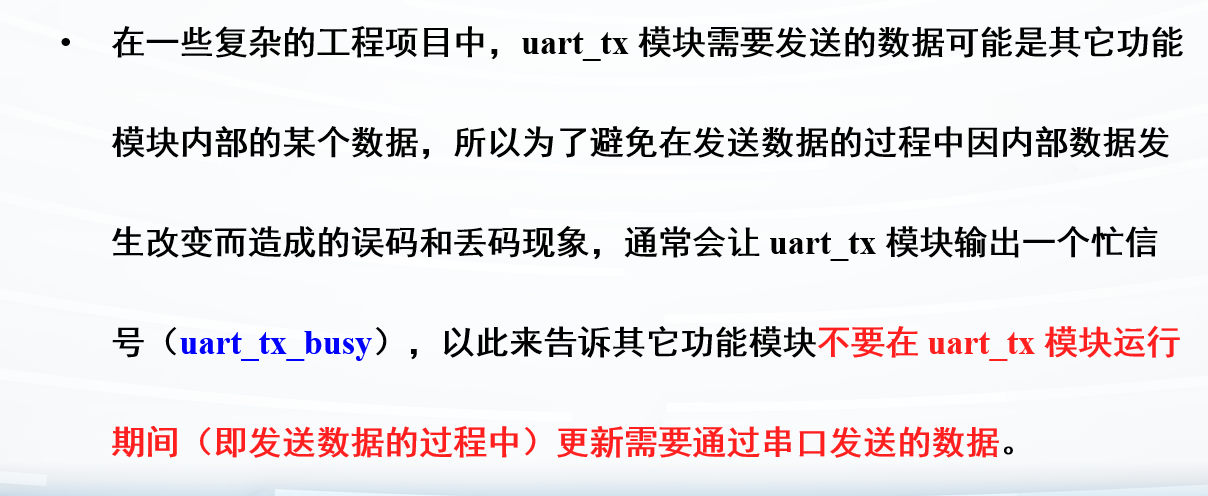
参考资料
课程PPT

